GIGABYTE GA-X99-SLI, A Closer Look
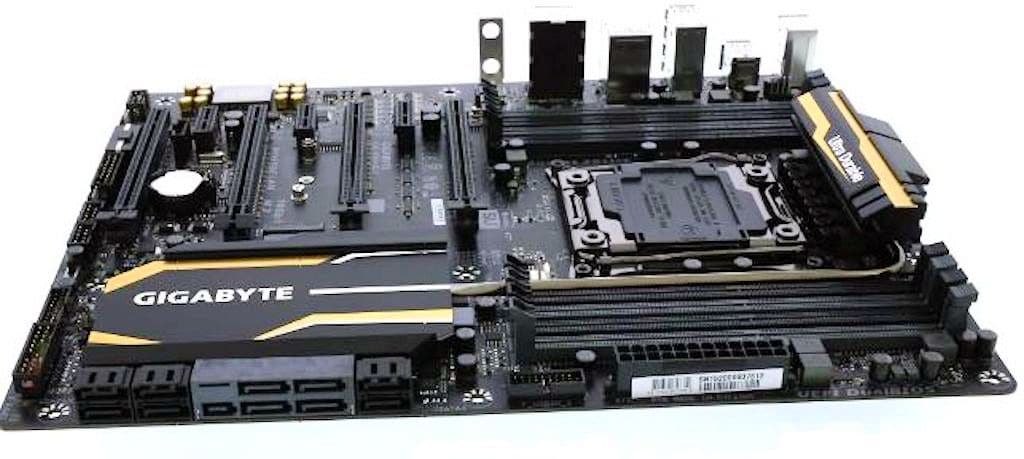
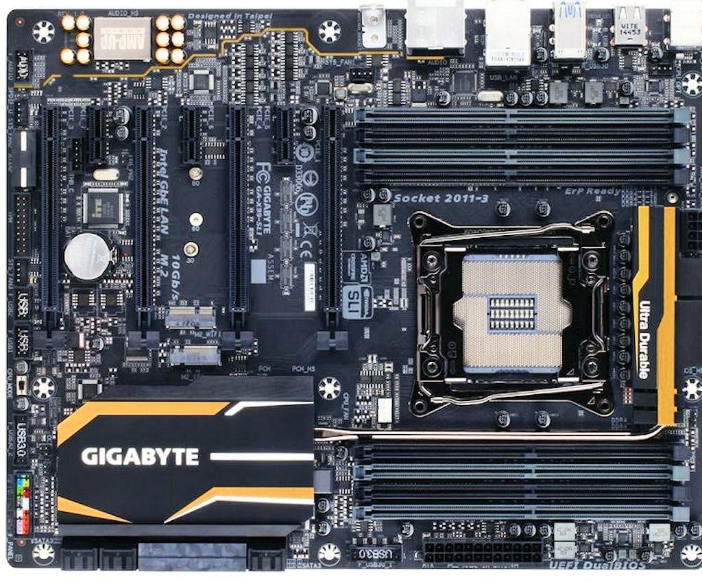
At first glance we see an enthusiast-based motherboard for the newest hottest hardware, but served up in an old school fashion. Four PCI-E slots, eight RAM slots, a slew of SATA ports, and little to give away the enthusiast nature of the beast until you get down into the close up features.
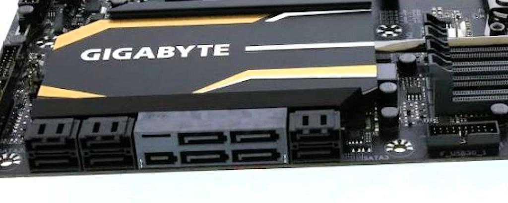
While the GIGABYTE X99 SLI has SATA Express and six SATA ports, you might as well count them as 10 SATA ports, unless you happen to be inventing your own SATA Express drive. Above we get a peek at GIGABYTE’s newly redesigned heat sink and just to the left edge of the USB 3.0 connector.
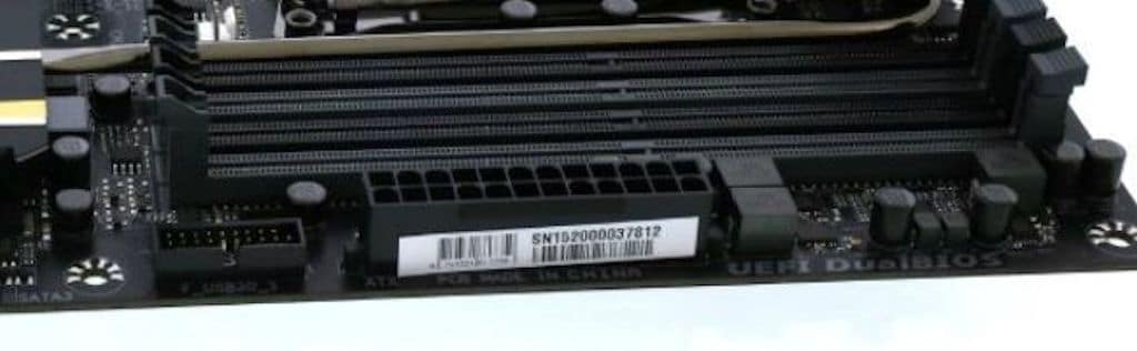
Off to the right of the USB 3.0 connector you have the 24-pin mainboard power connector and the capacitors and chokes that handle this set of RAM slots. Each set of 4 RAM slots will have a power setup like that.
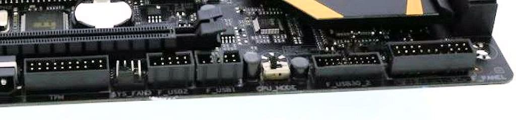
Turning the corner to the connector edge, things get quite busy and starting Right to Left we find the front panel connector, another USB 3.0 connector, the CPU mode switch, two USB 2.0 connectors, a fan header and a TPM connector.
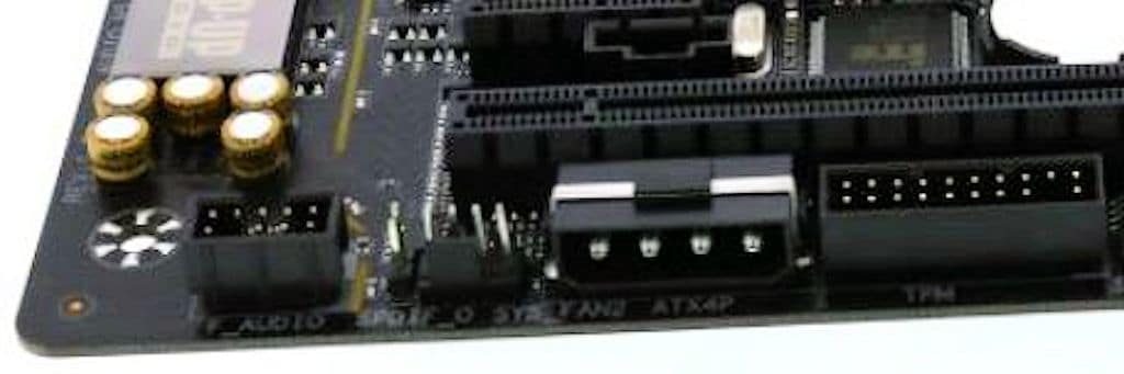
Just past the TPM connector is a feature we really don’t like to see: a 4-pin Molex plug to provide extra power to the PCI-E ports should you go with an extreme 4-way SLI configuration. Manufacturers and chassis builders have for years clung onto Molex connectors and inevitably you are left routing one Molex cable to the motherboard and possibly sharing it with some other legacy devices. We see no reason for not tossing a Molex to SATA power connector adapter in the box, or at least do away with the Molex and champion the SATA connector cause.
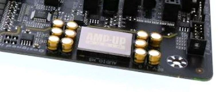
Here’s a good shot of the fine gold Nichicon capacitors for the ALC1150 audio and the AMP-UP amplifier setup providing a level of sound even audiophiles can enjoy.
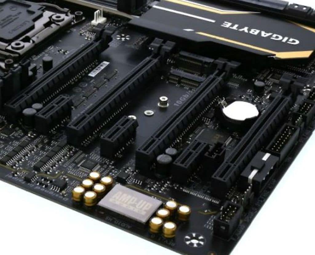
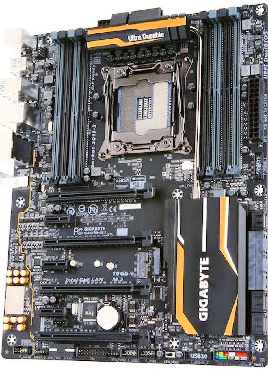
Getting to the PCI-E area we find four full size x16 PCI-E slots with three PCI-E x1 slots spaced between. Now two of those full sized slots will run at x16 and the other two at x8, but in the case of quad-SLI, some adjustment to that arrangement will have to be made. In 4-way SLI, you run a single x16 slot and three x8 slots. In triple-SLI you run x16, x16,x16, and in dual-SLI you have x16 and x16. On a full 40 PCI-E lane CPU that leaves eight lanes open for a PCI-E hard drive or various PCI-E cards you may want to add in, but you have to consider the M.2 HD Slot and the M.2 Wi-Fi slot there in the background.
PCI-E is the going currency for speed on motherboards, and CPU manufacturers need to see that and open up the 60 or 80 PCI-E lanes so we have less “What PCI-E goodies can we use?” decisions to make. We can see a time when PCI-E is choked with lightning fast hard drives, Wi-Fi, Bluetooth, high-end audio cards and tons of enthusiasts wondering how they are going to get the PCI-E bandwidth to do it all.
Here again we see a fourth PCI-E slot so close to the connector edge that actual quad-GPU usage would interfere with using the connectors. We can understand maximizing board real estate, but how about revolutionizing and offering a 90 degree connector set for that edge. One generically designed set should cover most motherboards and be a good upsell for vendors.

Being a budget-friendly SLI board with high-end hardware, the rear I/O amenities are a little slim with legacy mouse and keyboard connectors. There’s four USB 2.0 ports along with three USB 3.0 ports, a BIOS Flashback port, the usual audio and optical ports, and a bracket for the WI-Fi and Bluetooth if you use the internal M.2 setup. We find ourselves wondering why GIGABYTE went to a M.2 Wi-Fi setup without making the WI-Fi/Bluetooth card part of the standard bundle. Most of us want at least Wi-Fi on a board, so pushing consumers to using a more expensive Wi-Fi/Bluetooth card when they can get a Wi-Fi/Bluetooth dongle for a USB port for cheap on Amazon makes no sense to us.
Perhaps there’s some super fast WI-Fi on the way we don’t know about, but we tend to think pushing wires to an external bracket through the electromagnetic maze of computing hardware would almost negate the speed advantage, not to mention leaving a wire traipsing across systems close to RAM and the primary PCI-E video slot.
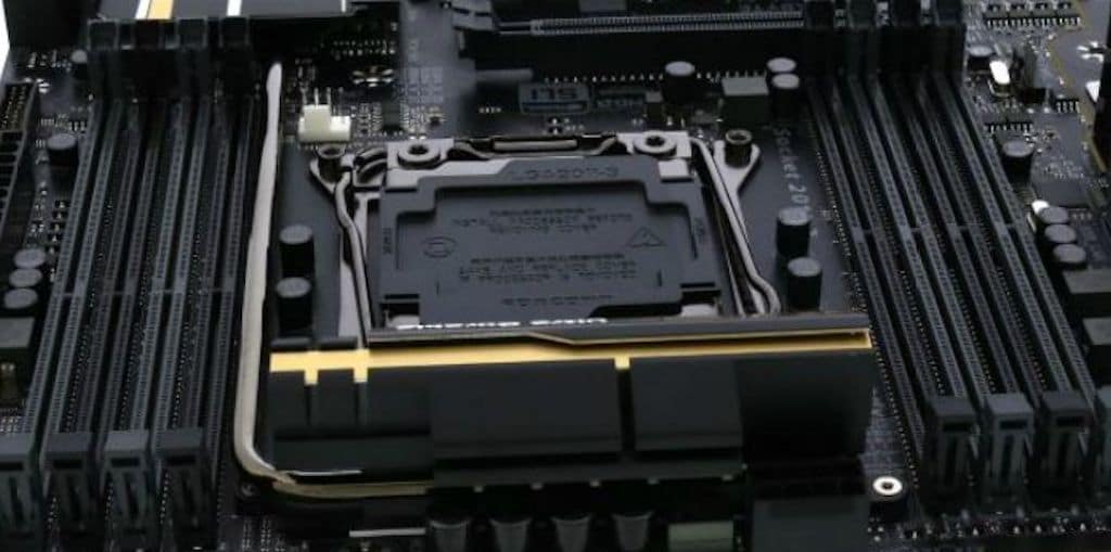
Looking into the CPU area we see the MOSFET heat sink covering those geek candy ProlRstage IC’s and server quality chokes. International Rectifier is the manufacturer of choice for the CPU power components and currently the ProlRstage MOSFTEs single package design is state of the art. Most of the motherboards we’ve seen with all digital power controllers of this quality tend to be more to the $300+ price range and the same setup on some competitors boards will run you double what the GIGABYTE X99 SLI board will cost you. Now of course for your extra $200-$400 on those higher end boards you do get a bank of on-board switches and a double digit debugger, but as far as hands-on options to get the OCing job done, this board has everything they do.
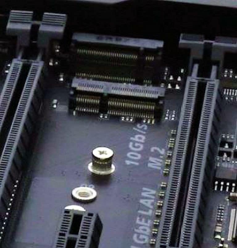
Here’s a close up shot of the M.2 HD slot and the M.2 Wi-Fi card slot. We find ourselves hoping that video card deck height and aftermarket coolers on GPU’s clear those slots when populated. We’ll withhold judgement until we have the Wi-Fi card in hand, but that setup looks a little close for comfort.
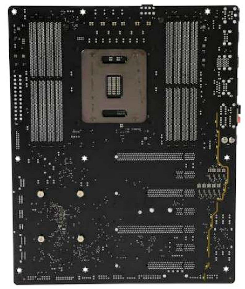
The back of the GIGABYTE X99 SLI is fairly unremarkable, except for the light brown data path which is likely part of the ambient lighting for the audio setup.
Looking at a top down shot of the GIGABYTE X99 SlI, the layout looks a little less crowded than a lot of the higher-end enthusiast boards. What we’ve found on the ultra high-end boards is unless it’s an out of chassis overcolocker, most of the extras don’t mean much once the case door is shut.
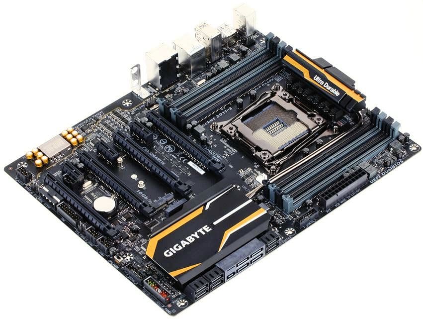
With the board tilted just a bit you can see how close the fourth PCI-E slot is to the edge, so you are going to be lucky if those can be used with a quad-GPU configuration. Of course quad-SLI is pretty rare, so it won’t be an issue for many people.
Overall, the look of the board has a muted feel to it and a couple of spots are a little cramped, but today’s boards are the definition of cramped. It just might be time to design another standard for form factors on motherboards.
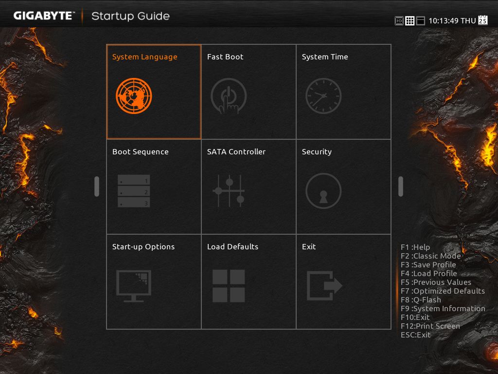
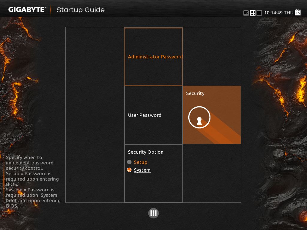
GIGABYTE X99 SLI BIOS
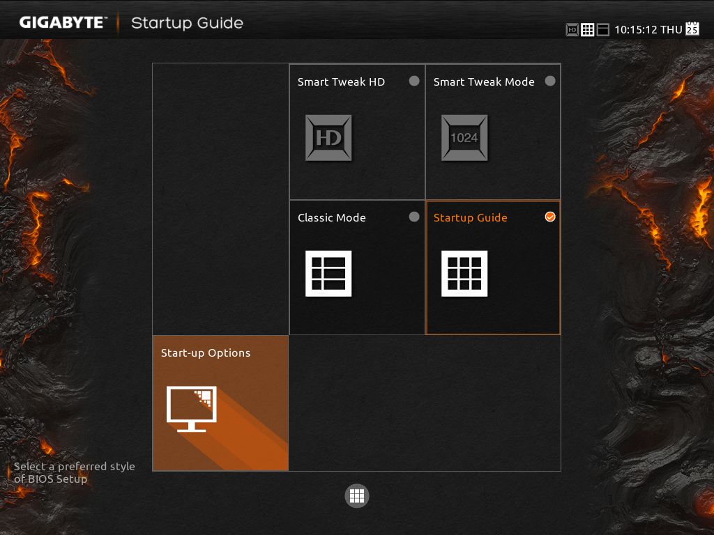
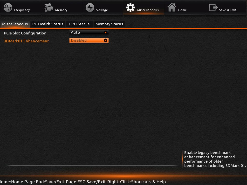
Lets start the BIOS section with a little peanut gallery commentary: this is the initial BIOS, but a Beta BIOS is available. The Beta BIOS just changes some memory configurations having to do with 16GB RAM modules. GIGABYTE saw fit to include a classic M.I.T. BIOS style, an Easy BIOS (Startup Guide) method, and a UEFI BIOS style. We can understand an EASY BIOS method for beginners. In regards to the UEFI BIOS, we love it, but in most cases it needs to be simplified. That’s the case with the GIGABYTEe X99 SLI. It overwhelms with options, many of which the average user and experienced OCer will never look at. So much time was spent programming different versions and views for this BIOS that GIGABYTE may have been better off concentrating on an Easy BIOS and a UEFI BIOS with a unified OCing screen. In all fairness, a unified OCing screen is missing from most vendors’ BIOS, and you end up flipping back and forth across several pages digging through options that you will never use.
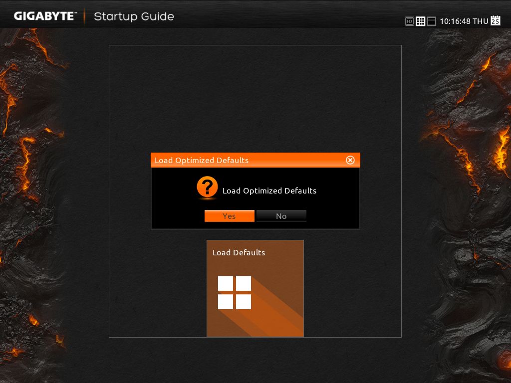
We can only hope that as the board matures, a unified OCing screen appears with it. If you don’t believe us, take a look at the 30+ BIOS screen shots it takes to cover it.


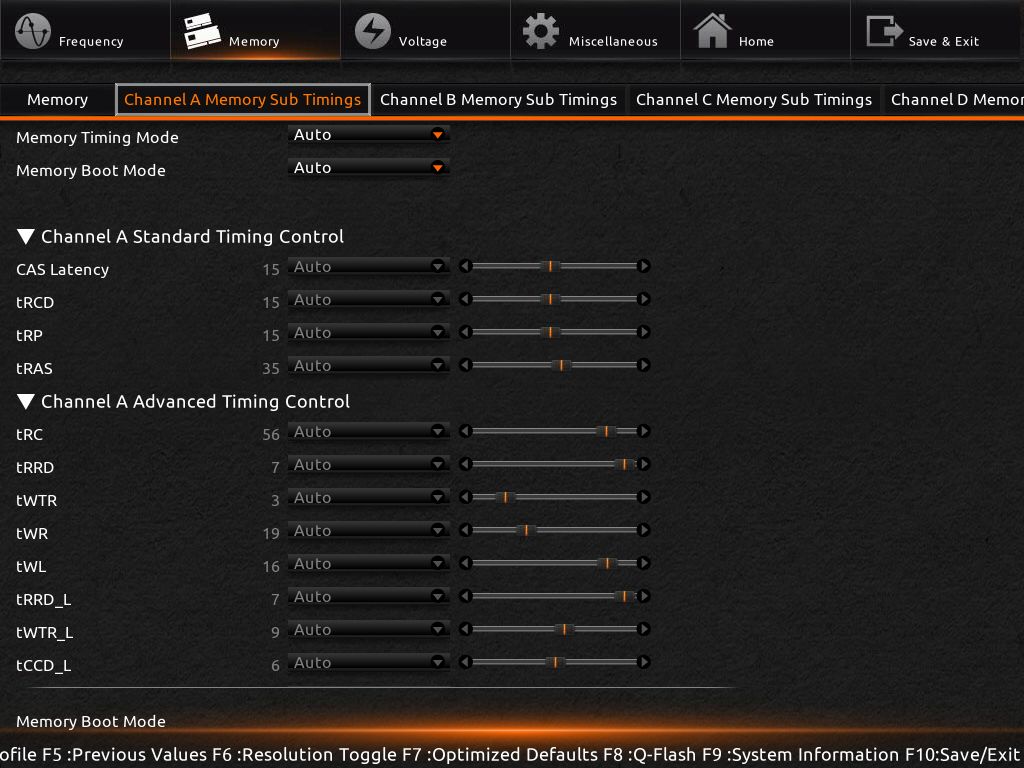
All of the Channel Sub Timings screens are exactly alike so just channel A is pictured here.

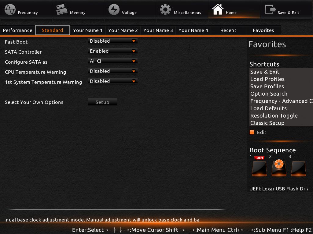
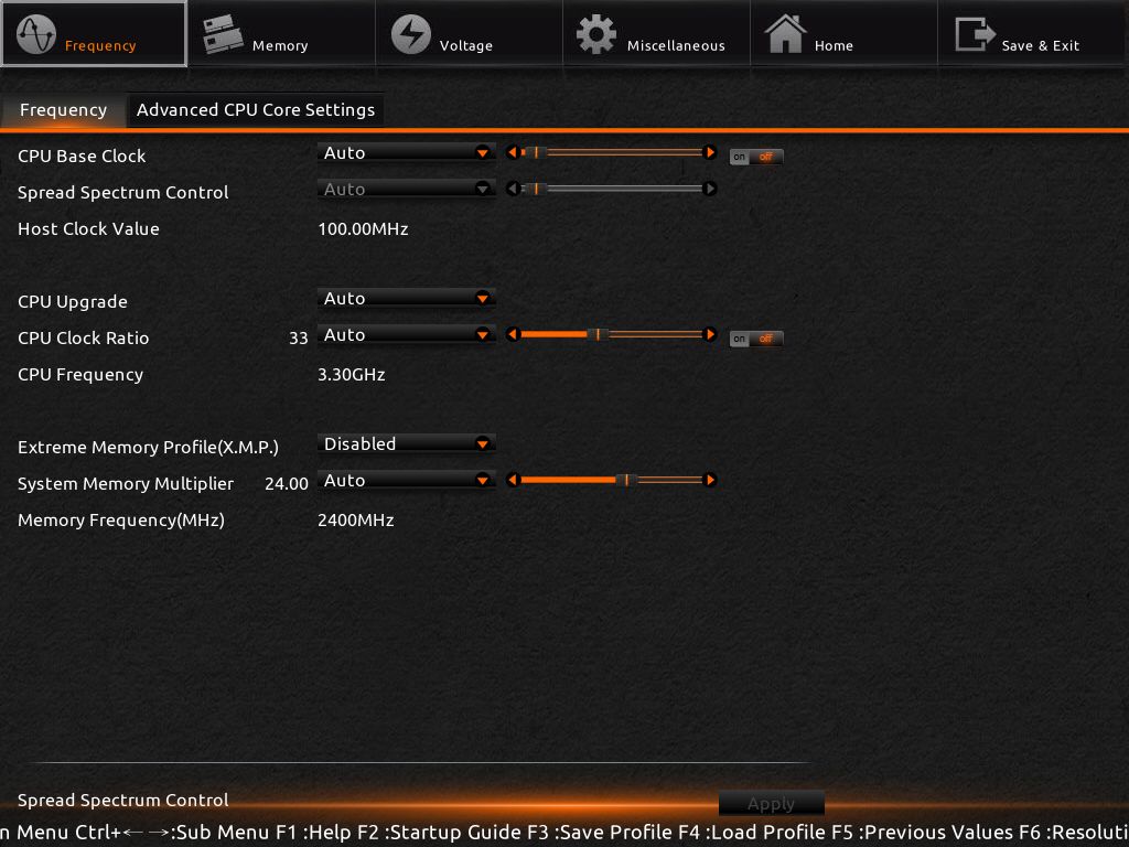
Switching to Classic M.I.T. BIOS Mode.
![Advanced Frequency Settings_[10-22-33]](https://bjorn3d.com/wp-content/uploads/2015/06/Advanced-Frequency-Settings_10-22-33.jpg)
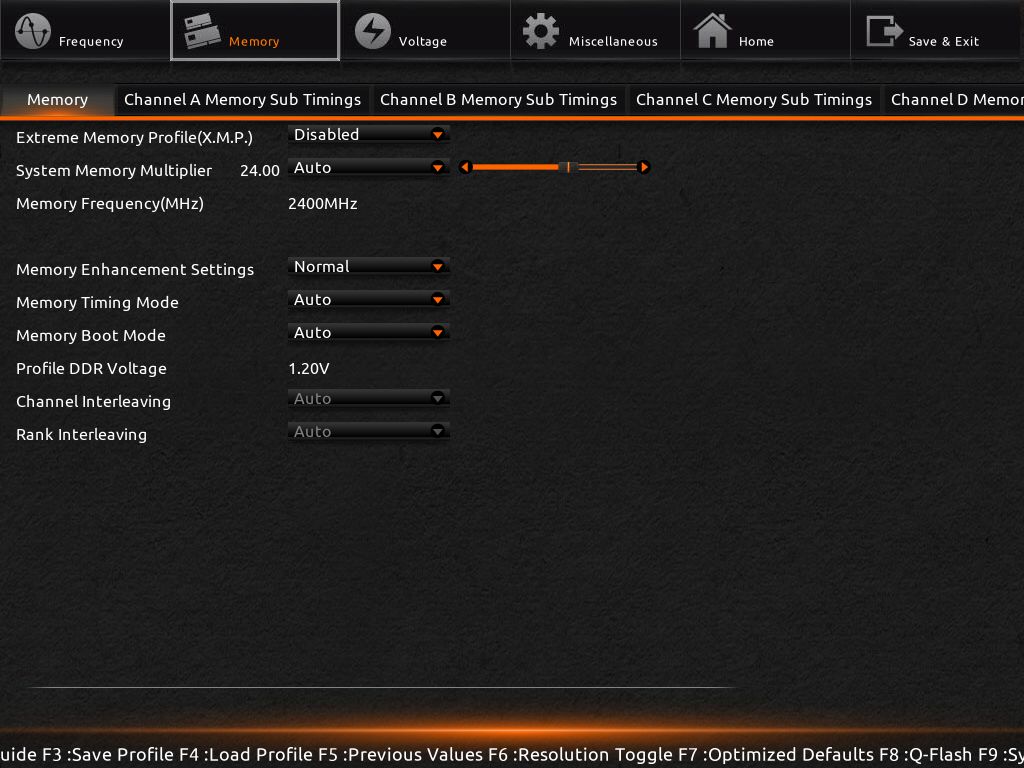
![Advanced Memory Settings_[10-22-54]](https://bjorn3d.com/wp-content/uploads/2015/06/Advanced-Memory-Settings_10-22-54.jpg)
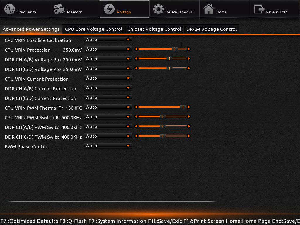
![Advanced Power Settings_[10-23-45]](https://bjorn3d.com/wp-content/uploads/2015/06/Advanced-Power-Settings_10-23-45.jpg)
![BIOS Features_[10-27-16]](https://bjorn3d.com/wp-content/uploads/2015/06/BIOS-Features_10-27-16.jpg)
![Chipset Voltage Control_[10-24-39]](https://bjorn3d.com/wp-content/uploads/2015/06/Chipset-Voltage-Control_10-24-39.jpg)
![Chipset_[10-27-33]](https://bjorn3d.com/wp-content/uploads/2015/06/Chipset_10-27-33.jpg)
![CPU Core Voltage Control_[10-24-11]](https://bjorn3d.com/wp-content/uploads/2015/06/CPU-Core-Voltage-Control_10-24-11.jpg)
![M.I.T._[10-21-53]](https://bjorn3d.com/wp-content/uploads/2015/06/M.I.T._10-21-53.jpg)
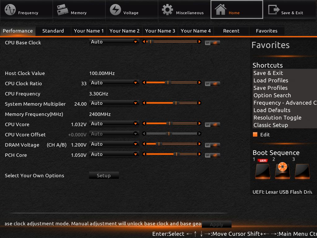
![Main_[10-27-04]](https://bjorn3d.com/wp-content/uploads/2015/06/Main_10-27-04.jpg)
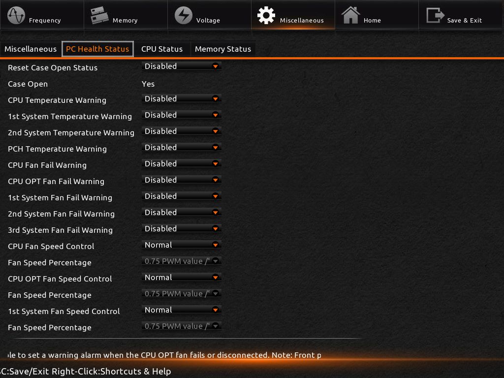
![PC Health Status_[10-25-17]](https://bjorn3d.com/wp-content/uploads/2015/06/PC-Health-Status_10-25-17.jpg)
![PC Health Status_[10-26-23]](https://bjorn3d.com/wp-content/uploads/2015/06/PC-Health-Status_10-26-23.jpg)
![Peripherals_[10-27-24]](https://bjorn3d.com/wp-content/uploads/2015/06/Peripherals_10-27-24.jpg)
![Power Management_[10-27-41]](https://bjorn3d.com/wp-content/uploads/2015/06/Power-Management_10-27-41.jpg)
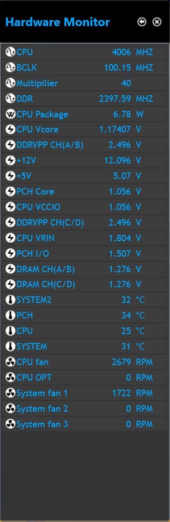
This isn’t part of the BIOS, it’s the GUI Hardware Monitor. Notice the RAM Voltage at 1.27V. We had voltages set at 1.2V by XMP, manually and in the EXTune software, and no matter what we did, the board kept setting it to 1.27V. Be it the initial BIOS or overvolting to cover VDrop, this board boasts all-digital power control, and when we set a voltage to 1.2V, we want it exactly at 1.2V. Period. No questions asked.