
Packaging


The packaging is pretty standard fare with the lift open design like we have seen on many models previously form the ROG side.
Accessories


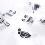

The accessories with the Maximus XI Extreme are plentiful but there are some special callouts here.
- DIMM.2
- This has been redesigned as it how has a heatsink which helps keep speedy drives cool and also, strangely enough, makes it look like an extra thick DIMM
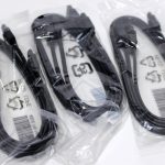
- Sleeved SATA Cables
- The board comes with 4 standard plastic sheathed cables but also two fiber sleeved units which will be a nice aesthetic for those still employing SATA based storage.
- ROG USB Drive
- Yes ASUS has been doing this for a while but it is still awesome and so many still do not do this. having all of the drivers on a USB is a huge help as many builds do not include optical drives any longer.
- Fan Extension board
- This connects to the motherboard and uses a 4 Pin PATA connector to give you a motherboard controllable extra 4 fan connectors and also temperature probe connections.
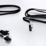
- RGB Extension cables
- I know RGB cables may not seem like a big deal here but I really like the fact that ASUS goes ahead and includes an extension cable not just for 5050 4 pin headers but an extension for addressable RGB as well.
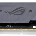
The Board
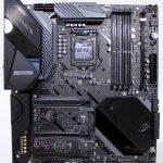
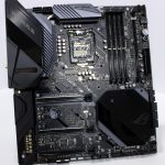

Here we get our first view of the complete board. While the massive size of the board may be the first thing to enter your mind as it did mine, I also quickly noticed how densely packed every inch of the PCB seems. ASUS did not make this board just to be big, they crammed it full of hardware.
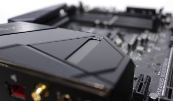
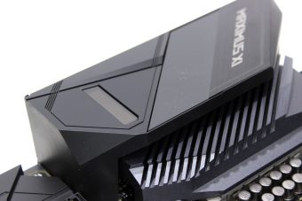
A Closer Look
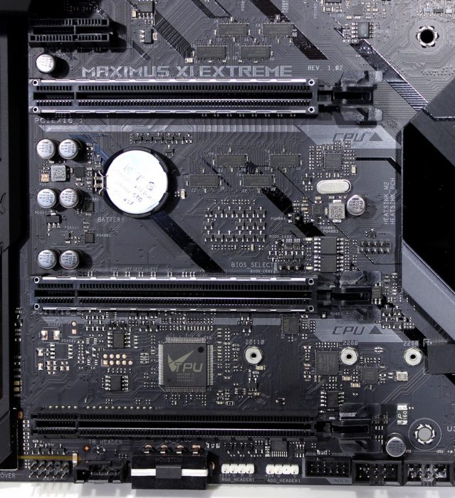
The Maximus XI Extreme has three x16 mechanical slots. the top two are CPU fed slots while the last is chipset/DMI. It is worth noting that even though the slots are mechanically x16 they are electrically dependent on slot and device population. The topmost slot is the primary and when the 2nd slot is not populated it will give 16 lanes PCIe to the installed GPU or other devices. However, since this board employs a DIMM.2 it is worth noting those are CPU lanes as well so if you populate two M.2 Drives in the DIMM.2 module your main slot will drop to x8. Keep this in mind as this means if you are running SLI, you will need to use the DMI based M.2’s below the PCH cover. This is not a limitation of the ASUS board but the platform as a whole since mainstream platforms do not have the massive quantity of PCIe lanes available like we see on the HEDT parts.
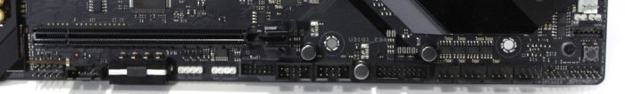
The lower edge of the board houses large swath of connectivity. (Left to right)
- Front Panel Audio Header
- Thunderbolt Header
- 4 Pin PATA Supplemental power
- RGB 4 pin (5050 style) header
- RGB 3 pin Addressable header
- ASUS NODE header
- 2x USB 2.0 headers
- USB 3.0 20 pin header
- 4x Radiator fan ports
- Post-Speaker Header & Thermal probe Connector (Above)
- Front panel header & Bios Switch Button (Above)
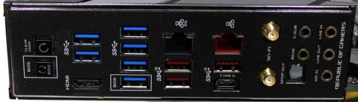
The rear panel I/O is nothing to scoff at as it has a full load of high-speed connections. (Left To Right)
- Bios Flashback Button (bottom) CMOS Clear Button (top)
- HDMI Port for onboard Intel GPU
- 6x USB 3.1 Gen 1 Type A ports
- 3x USB 3.1 Gen 2 Type A ports
- 1x USB 3.1 Gen 2 Type C port
- 1x 5Gb RJ45 port (powered by Aquantia AQC111C)
- 1x 1Gb RJ45 port (powered by Intel I219V)
- Dual WiFi/Bluetooth Antennae ports (powered by Intel AC 9560)
- 8.1 Channel gold plated audio ports w/ S/PDIF Optical port (Powered by SupremeFX S1220) aka Realtek ALC1220
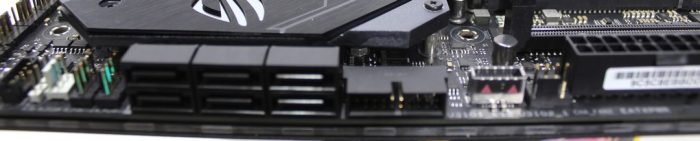
The storage side of things we find 6x SATA ports right above the Water pimp/Flowmeter headers for the water cooling zone. To the right of the SATA, you have another USB 3.0 20 pin header and also a USB 3.0 Gen 2 onboard header.
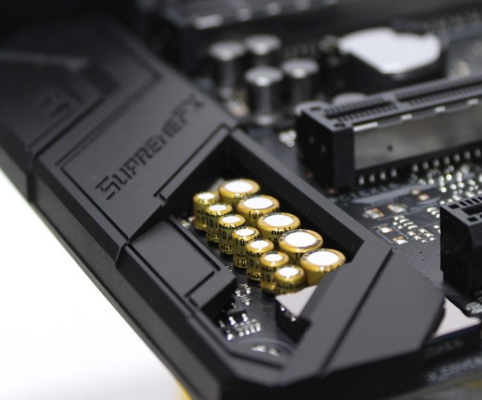
The SupremeFX audio solution has a large array of Nichicon caps along with other goodies to help give a better than meh experience for audio duties. That’s not to say its the end all tell all but ASUS have gotten progressively better in their audio solutions and in ensuring they have some solid component choices in place when building out their studio solutions.
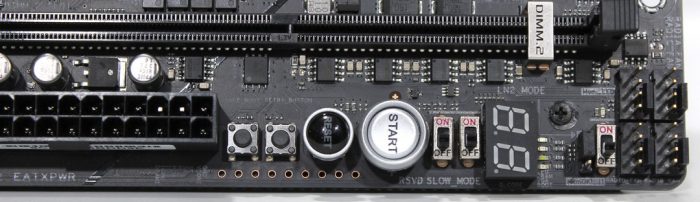
The top right of the PCB on the Maximus XI Extreme is no joke and still home to what I call the “Overclockers Corner” as it has most of the controls you would be interfacing with during an XOC session or while in a testbench setup. (Left to right)
- Safe Boot Button
- Retry Button
- Reset Button
- Power Button
- RSVD Bwitch (CBB)
- Slow Mode Switch
- Post Code Display
- 4 LED post status indicators
- LN2 Mode Jumper
- MemOK II Switch
- 4x Radiator fan ports
Here we have the “LiveDash” display which shows in real time various information which you can configure. during post it shows text descriptions of the position in the post process which it is currently performing.
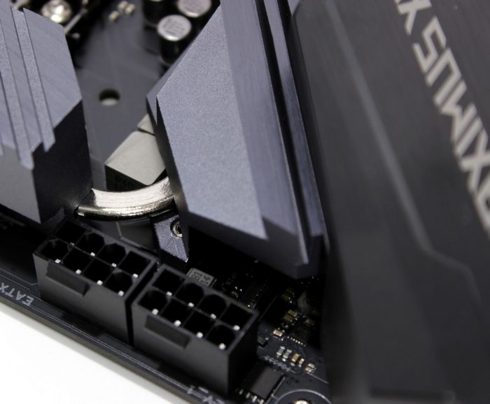
Here you can see the Dual 8 pin power connectors to feed the beast. Now do keep in mind that any system even liquid cooled does NOT require you to connect both connectors as you would likely be well below the amperage needed (200A @ CPU power stage) to employ a 2nd. but there really is no harm in connecting them. If using this board in an XOC environment I would advise connecting both to ensure you don’t stress a single cable too badly but even then I don’t think it will really pull that much. so basically any system you will use every day will likely not need the dual 8 pin, but if you have it and can connect it, no reason not to.
Lets pop the top and see what is under the Extremes covers.


I seem to be having a bit of a situation with this board and I thought you might be able to help. It would seem that somewhere I’m not sure if it’s in the Bios or if it’s on the board that for an m.2 slot there’s a switch between usb and pcie. Currently mine is at usb and I would like to change it pcie.
Thanks if you can help.
Also I was wondering if I upgrade the BIOS does it change all the settings back to default?
Normally I would save a BIOS profile before flashing and set it to defaults to relieve the variable which may cause a bad flash.
Also, there is no USB signal at all going to an M.2 slot, can you please further explain what you are referring to?