Fractal Design Meshify S2


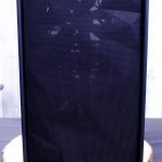
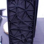
The Meshify S2 right out of the box impression. From the front looks like a Meshify case as you would expect. Carrying stealth-inspired angular grille. Moving around to the interior and it is basically the Define S2 inside and out.
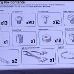
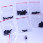


Here we have the accessories which come in a box that also tells you the contents via pictograph. This means you can do a quick visual check without even consulting the manual.
Listed Left > Right and Top > Bottom
- Accessory Box
- Screws and Other Parts For Installation
- Zip Ties
- Reservoir Brackets
- Fractal Window Cloth
- SATA Extension Lead
This is pretty standard fare for a chassis with the addition of the reservoir brackets and the SATA Extension.
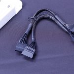
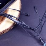
Here you can see the extension cable as it is meant to be used as it allows a clean cable run to all 3 3.5″ bays should they be populated.
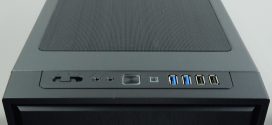
Here is something on the Mshify S I am rather disappointed in. For anyone familiar with the Define S2 or the R6, you will undoubtedly know that you can strip the case down including the front panel to build it how you want. Well with the Meshify S2 for some reason Fractal bucked tradition and integrated the I/O into the front panel which means if you want to completely remove the front panel to build you have to pull all of the front panel cabling out of the case. This makes even the most rudimentary maintenance in the front area a much more involved process unless you want to just swing it out of the way by the very little slack you have and hope you don’t scratch the front.
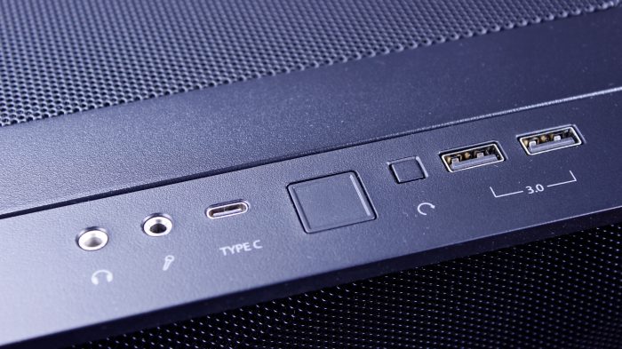
The next part of disappointment is that the Define S2 which this is the namesake had
- 2x USB 2.0
- 2x USB 3.0
- 1x USB Type C 3.1 Gen 2
The Meshify S2 for some reason gets neutered down to two Type A ports and a Type C. To many this may be a non-issue but is a similar price point, I would expect the connectivity to be similar. If Fractal happened to be worried that users may not want USB 2.0 then, go ahead and place dual pairs of 3.0 just so that users who need connectivity for whatever peripherals they don’t want to reach around the case can have the option on the front.
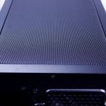
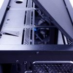
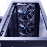
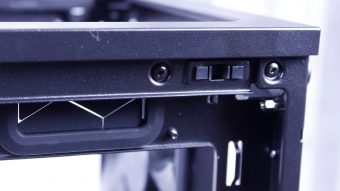
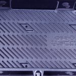
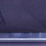
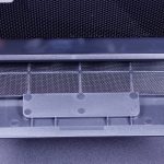
Here you can see the Meshify S2 top filter mesh which is the exact same release type as the Moduvent on the R6. I actually kinda wish my R6 came with this mesh top as I like it a lot and doesn’t have the gap my Moduvent has with the solid portion removed. Next up after removing the filtered top, we find the removable fan/radiator tray. This can be removed with 4 screws and lifts right out leaving a massive hole. A quick tip, if you are building in this case and not planning to install a top mount radiator, still remove these parts during the build as it means you have much more wide open access to installing parts in the chassis.
One thing to note is that while the top will support a 140mm based radiator it will interfere with taller memory DIMMs so it might be best to stick to a 120mm based liquid cooling radiator unless you know your DIMMS will clear.
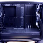

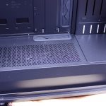


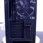
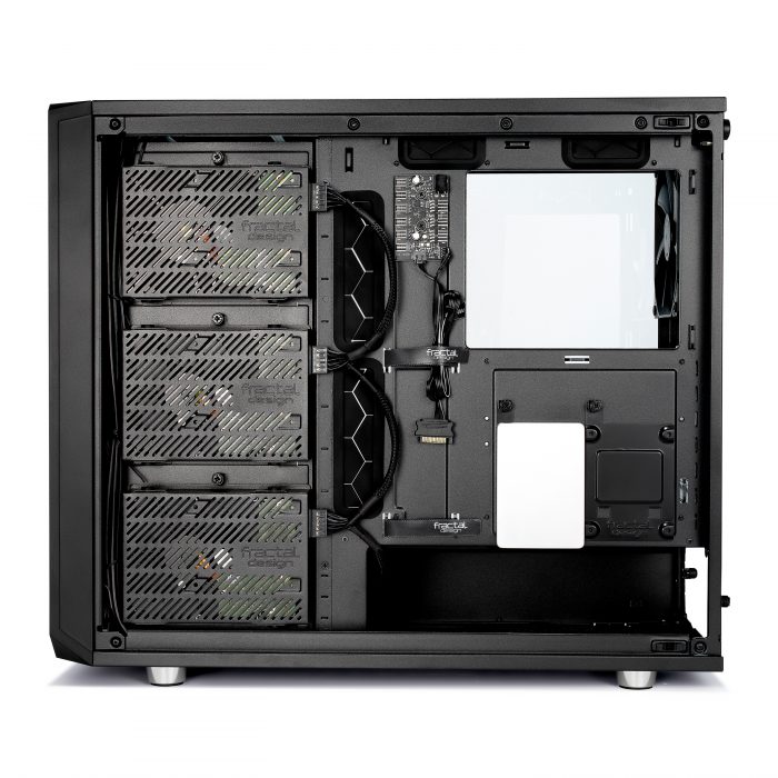
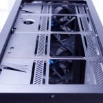
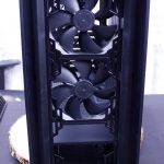
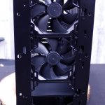
Here we have the interior of the bare chassis. the vertical slits are meant to be used for the included reservoir brackets. This case was definitely meant for liquid cooling enthusiasts and that makes me happy as its a high airflow concept case with plenty of room to build what you want. The front comes with dual 140mm fans while the rear sports a single by default.
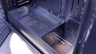
The PSU shroud is full length although the front most portion can be removed to fit larger radiators in the front/bottom area.
The rear I/O has seven total normal slots with two set for vertically mounting your GPU if you want that. The vertical riser is sold separately so keep that in mind.
The CPU cooler cutout in the motherboard tray is absolutely huge. If you cannot work with your backplate with this cutout, then there is something seriously strange going on.


Here we view the rear of the motherboard tray area.
First up with the total overview you can see the 3x 3.5″ cages which can also each mount a 2.5″ drive if you don’t have any mechanical spinners to put in there.
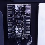
The fan hub area is powered by a SATA power lead and uses a PWM header to the motherboard to help control attached fans. The hub sports 3x 4 Pin PWM headers and 6x 3Pin DC fan headers.
The rear area has a ton of tie down points all around the perimeter of the chassis with two large velcro straps going vertically through the center of the rear compartment.
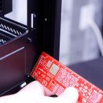
For checking the cable management space I have the “keycap rule”. If you cannot fit a keycap comfortably into the cable management gap its nit wide enough for enthusiasts. As you can see it is more than enough. P{ulling out the PCB ruler verifies we have just shy of 20mm at the lip with some areas losing a few millimeters here and there but overall plenty to hold all but the most demanding fat sleeved cables.
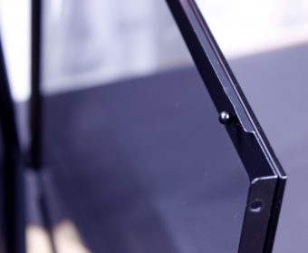
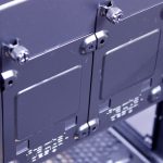
The side panel I quite like as it is a full glass panel with no thumbscrews or nuts on its surface. the side panels can be secured with thumbscrews in the standard rear position for security, but otherwise, on the trailing edge they use a ball and socket retention. these have a solid clunk when pressed closed and had me plenty confident that it would retain the panel. the front has a U channel which pivots on the rounded front edge so that the panel swings out and off the ball and socket like a car door.
The cabling was retained by the perimeter and the bottom-most 3.5″ bay which also held the accessories box. once removed we get a better look at the drive mounting options first.
The 3.5″ tray requires inserting rubber grommets and then screw through them to mount larger mechanical drives.
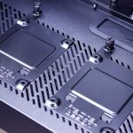
The two included 2.5″ SSD trays are mounted on the rear but can also be swapped into slots on the PSU shroud should you have SSDs you want to show off.
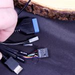
The cabling which was tightly cinched in place also hid the front fan cables I did not even notice until later when I was building the rig. they are coiled up and tucked under the front panel cabling, which some less experienced users may think they have connected already due to the fan hub and the lack of visible cabling.
The front panel cables are as follows
- Front panel Switches and HDD./power LED’s
- USB 3.0 20 pin cable
- USB 3.0 Gen 2 cable
- HD Audio Connector
This connects everything at the front end as mentioned previously.

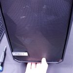
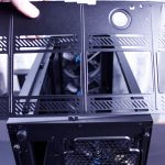
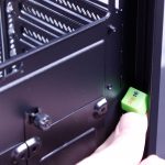
Here we see the front of the chassis and while unassuming it does hold some cool stuff. First off if you reach under the front you will find the full-length slide out dust filter. Once the dust filter is removed you can then reach under the front panel and locate the clip that releases the front mesh. After this, you reach to the bottom again and with a firm pull, you can release the clips holding the front frame off to see the complete front metal of the chassis. You will notice in the image just out of frame I am holding the front panel up and how little slack there is to move the front panel without removing all of the cabling.

Here you can see the front area of the PSU shroud which can be removed with two screws. The two screws are accessed after removing the front panel. this area allows access to the lower under PSU shroud area where Fractal says you can also install up to two fans or even a 280mm radiator, although the access to this area is limited and installing fans down here seems a little strange as without the panel removed you would just be ventilating the PSU shroud area.