I knew with my woodworking skills I would be able to create something with more style and presence, and even improve on existing case layout and cooling, however after giving it some thought I wasnt convinced that a wooden box mixed with the surroundings of a sleek monitor, keyboard and speakers, would be all that fitting.
WHY A WOODEN PC ENCLOSURE ?
The idea for a wooden computer came about while I was looking for a new case, alas every design looked very similar, and there were very few designs that actually looked strikingly different. I knew with my woodworking skills I would be able to create something with more style and presence, and even improve on existing case layout and cooling, however after giving it some thought I wasn’t convinced that a wooden box mixed with the surroundings of a sleek monitor, keyboard and speakers, would be all that fitting. Instead I thought it would be more suitable that I painted the computer I was going to design with a high quality solid gloss finish, to give it the appearance of metal, and my design would merely be a prototype to a later made professional metal case.
IDEAS & DESIGNS
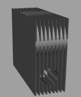
For the design to stand out from existing cases it couldn’t be square and conventional. so I started out with a quarter moon shaped design with a staggered top lined with fans, in theory this improved cooling as heat rises and that’s where the majority of the fans would be. However the design still looked amateur.
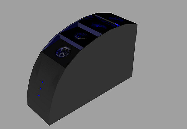
First Design … The Black Curve
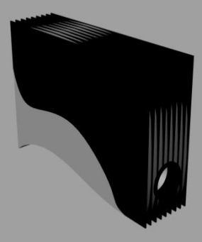
The second design I decided to go for all out cooling, and planned on integrating a 16” desk fan into the side. With radical styling the shape was almost circular, completely unique with unbeatable cooling, this should have been ideal. Unfortunately, a fan of that size would create a lot of dust inside the computer and the electromagnetic field produced by the fan motor may have had a negative affect on the components, and I still wasn’t content with the design.
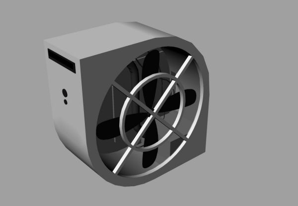
Second Design … The Big Fan Case
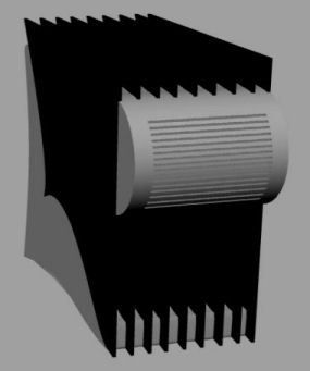
I wanted something more sleek, and fitting with the current trend of computer design, as I browsed computer shops searching for inspiration my criteria changed. I would now go for something a little more traditional and designed a series of cases that were typically square but I had integrated a car heater fan.
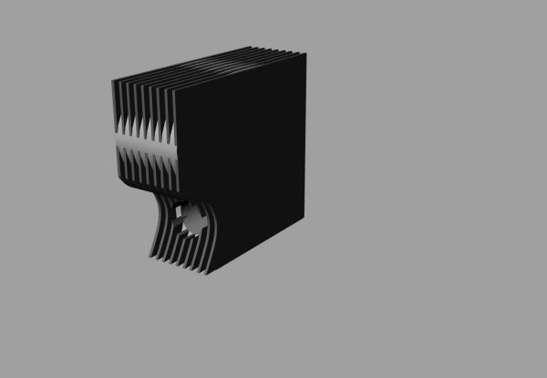
Third Design … More Traditional
p>The air produced by that would be siphoned on to the processor, and the large circular shape of the fan would jut out the front adding a little character to the otherwise square design. I added fins to the obscure shape to give it a completely square look, from the side it was plain and boring, but from the front it was totally unique, but as attractive as it was, the design was perhaps too complicated and it suffered the same dust and electromagnetic problems as the second design.
I came up with a number of designs, they were unique but still just a shadow of the inspiration they came from, the Lian Li PC-777 which is completely exclusive and like no other case which is what I was trying achieve, so once again the criteria changed. Unless I did something drastically different with the cooling I decided to keep it conventional and focused solely on coming up with a good design. After playing around with some shapes I came up with the final and perfect idea, it had a delicate curved back and top, the bottom was a mirror image of this and raised off the ground to allow for a intake fan to be placed discreetly, but in contrast the front was heavy and mean looking and featured a 12mm groove flowing through the whole thing linking it all together. The groove would let out a green glow of light, to give it a modern touch, to be in keeping with what it actually is, instead of disguising it as simply a cabinet. Double doors at the front would open to reveal the power button, usb ports, a cd drive and a 6.5” tft monitor to display vital temperatures and speed of the many fans.
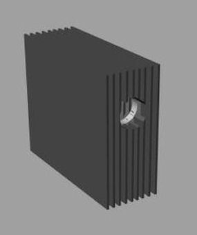
Alternative Designs
CONSTRUCTION
The wooden pc is constructed of 12mm birch veneer plywood, with the top being made of 0.8mm birch plywood with 3 sheets laminated together to form the curve. The front features 2 11x30cm doors that open outwards to 180 degrees, and when closed leave a 12mm gap, which is continued over the top of the case and underneath. There are 2 USB ports on the front and a illuminated stainless steel power button, there is also a large hinged side door, to access the interior.
The interior features a removable motherboard tray, with a wooden shelf directly above for the power supply. On the bottom there is a 120mm intake fan, and an exhaust on the back. Towards the front of the case there is a shelf for the cd drive, and below that is a suspend hard drive.
The exterior dimensions for the case measure 57cm from the base to the very top and 58cm from the front to the furthest point at the back. The case and components included weighs approximately 15.2kg.
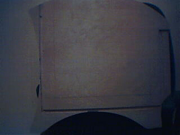
The first stage for making my wooden computer was to create a template out of 3 sheets of 2mm thick cardboard laminated together, the shape of the side was drawn on, and then cut out. It was crucial that the shape was smooth and perfect as I would be cutting round it, and any imperfection would be reflected onto the wood, however the maximum height it could be was 60cm due to the width the plywood sheets came in. As an overall height, 60cm provided ample space inside, however as there was to be a curved bottom, the interior space decreased and the original 60cm became very tight.
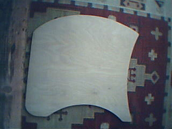
Stage 1 … Template on Side
I didn’t plan the technical aspect of the design at all, I simply made sure the components would fit, then just worked it out as I went along. Therefore the first step was to transfer my template from cardboard to wood. To do this I stuck the template on to a sheet of birch plywood using double sided tape, and using a router fitted with a 14mm bush, and a 12mm straight cutter I steered it round the template cutting down a few mm at a time, the result produced a perfect replica of the cardboard template.
Once I had cut out both sides I had to plan the interior lay out, the accuracy of this stage was essential, as the vertical space was already tight. I contemplated re adjusting the layout as it didn’t look as if there would be enough room for the motherboard and power supply to be arranged in the usual fashion, but there was plenty of space horizontally, however I couldn’t come up with a suitable arrangement that would allow all the components to sit comfortably, so I decided to stick with the power supply being above the motherboard as is the norm, but simply reduced the space between them.
Stage 2 … Slots Routed
Once the layout had been drawn on to the plywood I cut out earlier, I proceed to rout out 12mm wide, and 6mm deep groves to house the bottom, back and front, I also cut a rebate along the top where I would cut a thin veneer for the curve. The whole design would be held together with just glue and good fitting housing joints. I experimented with a scrap piece of plywood in order to find a good width for the case, I wanted it to be wide enough to allow a nice gap behind the motherboard for cables, but not so wide it looked oversized.
I also cut a 12mm slot, 30cm high out of the side panel to allow the doors to be recessed in to the side, so they would be flush with the front.
Stage 3 … Starting to go together
I proceeded to cut the back front and bottom panels to the agreed width and balanced them in the routed grooves, this gave me a good indication as to how it would look and to be certain that I had gotten it the right width.
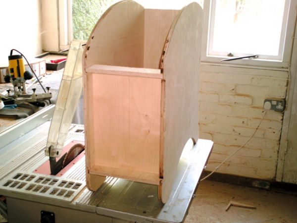
Stage 4 … Getting more together
Stage 4 … Side view
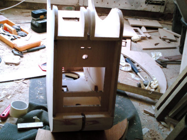
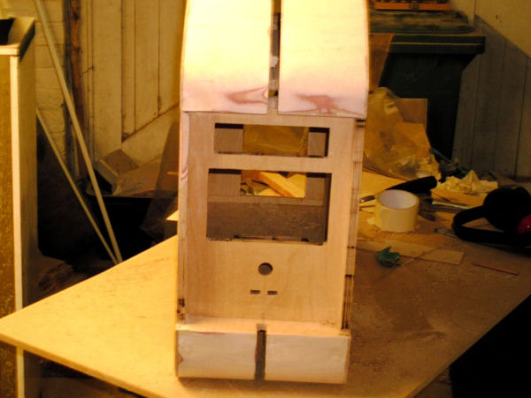
I was getting to the stage were I would be gluing it together, so I had to cut out all the holes and slots that I wouldn’t be able to do when its all put together. The first and most important holes to cut were to accommodate a 6.5” monitor and the DVD drive, I tried numerous techniques and wasted a lot of wood trying to get this perfect, the slightest blemish would stick out when coupled with the perfectly straight edge of the DVD drive. Initially I tried to cut the slot with a jigsaw, however it was causing the wood to splinter, and getting the perfect straight edge required was proving difficult, so I switched to the router and clamped a strip of wood down to act as a guide, all that was left was to square the corners using a chisel. Also on the front I drilled a 20mm hole for the power button and chiseled out a couple slots for the USB ports.
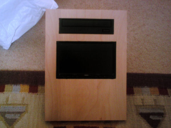
Stage 5 … Fitting CD & Monitor
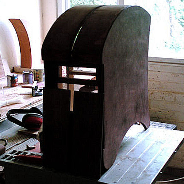
It was finally time to glue it all together all the slots had been cut in the front for the power button ect., along with all the slots in the back for the motherboard, and 120mm fan.
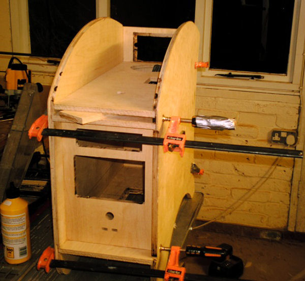
Stage 6 … Gluing It Together
Stage 6 … Back View
I allowed the glue to dry overnight and removed all the clamps, and I started to form the curved top, this proved to be more complicated then first thought, as I was having trouble bending wood around the tight profile. I tried various techniques including cutting the 12mm plywood down to only a few millimeters, but it still couldn’t withstand such strenuous bending, I also tried cutting groves across the plywood to allow it to flex, but it just snapped. Fortunately I discovered a company that sold thin birch plywood, and I purchased a 0.8mm sheet, which I would layer to form the curves.
The side of the case already had a rebate for the curved plywood to sit on, but I couldn’t simply lay the sheet across the top as there had to be a grove in the center, which would require some support in order to maintain strength. This was accomplished by cutting two, 22mm wide strips to the profile of the curve, they would be spaced 12mm apart to form the grove, and would hold the top in place, on the opposite side to the rebate. They were held in place using some fast setting polyurethane glue, and five minutes later I was on to forming the top itself. Fast setting glue was essential, as the regular PVA I was using would have taken too long to dry, and even by the time it had fully set the curved top may very well have moved. I cut the 0.8mm plywood to the required width, then glued it in place and held it temporarily with some tape, I was unable to clamp it due to the awkward shape. Three layers were required to bring it up the right thickness, I then cleaned up the edges with the router.
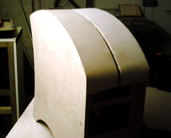
Stage 7 … Forming the Top
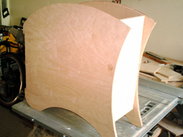
The underside was formed in exactly the same way, two pieces of plywood were cut to the profile of the side and glued in place 12mm apart, then the 0.8mm plywood was laminated together and glued on top. I only curved the front end as the back wouldn’t have been visible, and this wasn’t actually providing any structural support.
Stage 8 … Forming the Bottom
Once the top and bottom curves were completed I gave it a much needed sanding to give it a flush finish and left it overnight to fully harden.
Stage 9 … Bottom Completed
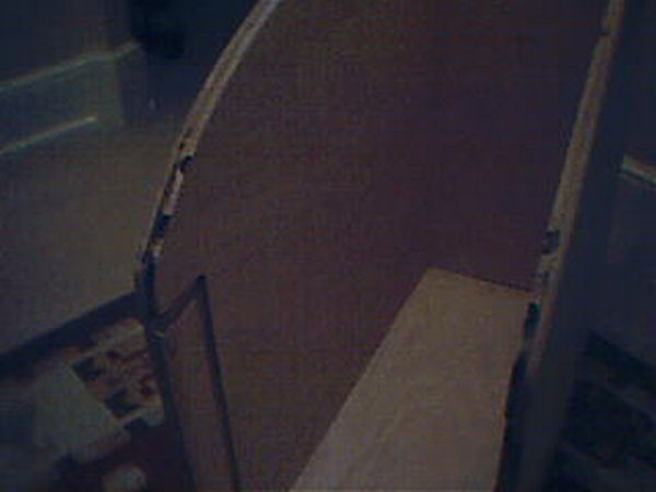
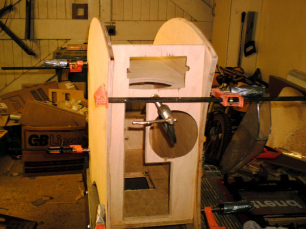
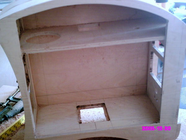
] After all the gluing had taken place I could then cut the large hole in the side for the door, again I did this with the router fitted with a 12mm cutter, I could have used the jigsaw, but it would have been harder to use a template, and would have splintered the wood.
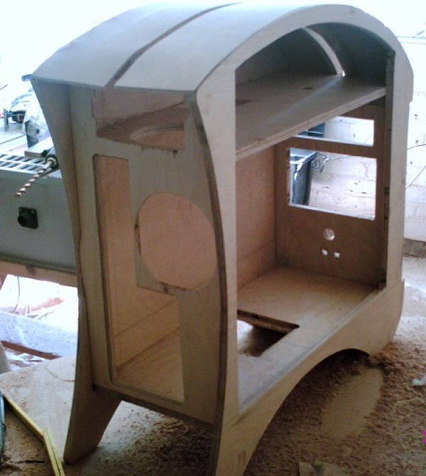
Stage 10 … Hole for back door view
Stage 11 … Hole for Door Side View
Stage 12 … The First Coat of Stain
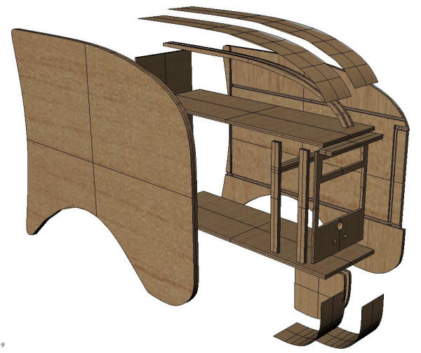
Explode Project Drawing
THE FINISHED PRODUCT


The wooden PC project has been successful, and is just as I had imagined it. It has changed from my initial design, mainly because the dimensions of the first design wouldn’t have worked as it would have had to be very tall to fit the motherboard and power supply, but also very deep to maintain a proportional look. I was also originally only going to give it a clear finish, and leave the wood its natural birch color, but I veered always from this as the dark stain covers up any blemishes in the wood, and compliments the chrome hinges and power button.
Although I am pleased with the outcome of the PC if I were to do it again it would be done quite differently. For starters, I would have focused on cable management far more than I have, such as a better space behind the motherboard, use some sort of cable clips to keep all the cables in place, and generally design the case specifically for the components. I would also like to improve and design a better CD and hard drive cage than the one I am using, which is simply a wooden shelf which the CD drive is screwed too and the hard drive hangs from that using hair bands. I would also like to experiment with the layout far more than I have.
COMPONENTS & PERFORMANCE
Here are the components I decided to add to my new treasure:
- Asus P5W DH Deluxe motherboard
- Intel e6300 core 2 duo @ 2.8GHz
- Scythe Ninja Plus Cooler
- 2 GB G Skill PC2-6400 DDR-2 SDRAM
- Connect 3d X1900XT
- Westen Digital 250gb hard drive
- Seasonic S12 430W PSU
- 2 – Akasa 120mm fans
- Nesa NSM 6.5″ monitor
- 2 – green cathodes
Are the old adages of wood being a poor heat conductor true? Of course they are, but not the the extent you might think! My motherboard temperature averages around 34 degrees Celsius at idle and my Core 2 Duo E6300 stays at a cool 23 degrees Celsius. At full load things warm up a bit with the motherboard edging up a few degrees to around 36-37 degrees Celsius and the CPU only heats up to 31 degrees Celsius thanks to the Scythe Ninja Plus cooler. Not as bad a you might think, huh?
FINAL THOUGHTS
The final design of the wooden pc has strayed a little form my original ideas, I don’t feel that the design has improved, but nevertheless it was necessary in order to have a successful interior layout. I would have rather made the case to the original specification, as I feel it had a much more sleek look, but it just wasn’t functional. In terms of practicality there’s no doubt a metal case wins, its cooler and safer, along with a longer lifespan, however the originality of the wooden PC is what makes it so appealing.


Hello, I am not sure you still check this posting, but seeing as I am considering building a wooden computer case, I thought I would try. Here are a few initial questions:
For starters, what motherboard tray did you use and did you really need to use it?
Where did you get the power switch from?
Did you consider having the power supply intake from the bottom of the case? If so, why did you decide against it?
When you say that the HDD was suspended using hair ties, what do you mean exactly (pictures would help immensely)?
What were the biggest challenges you faced building this case?
What would you do differently next time?
What would you recommend I do?