What’s inside?
Here we take a bit of a closer look into specific components on the board.
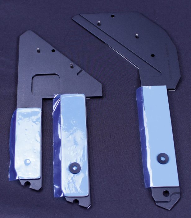
First part to get the ax was the lower M.2 Frozr plates which attach to the PCH sink with screws and have a thermal pad for each M.2 drive sitting in the slots below.
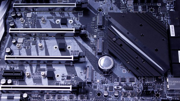
Here we have the naked PCIe slot area which also exposes the triple M.2 array with the above mentioned M.2 Frozr plates removed.
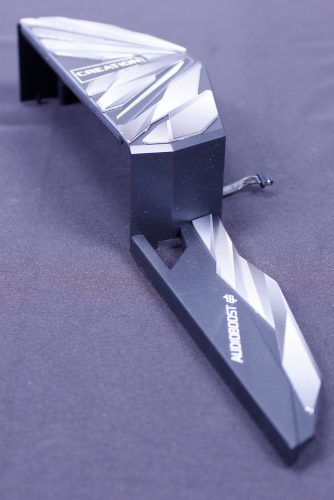
Next up, we removed all of the shielding and the VRM heatsink. The IO and lower audio shields are all one piece and come off together with the requirement to unplug the attached RGB cable before completely removing.
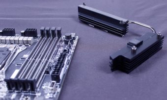
The VRM sink as you can see is two parts and is connected via a heatpipe. the lefthand side of the VRM sink is also used to cool the Realtek 2.5G NIC controller.
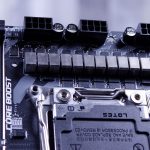
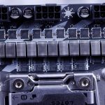
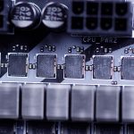
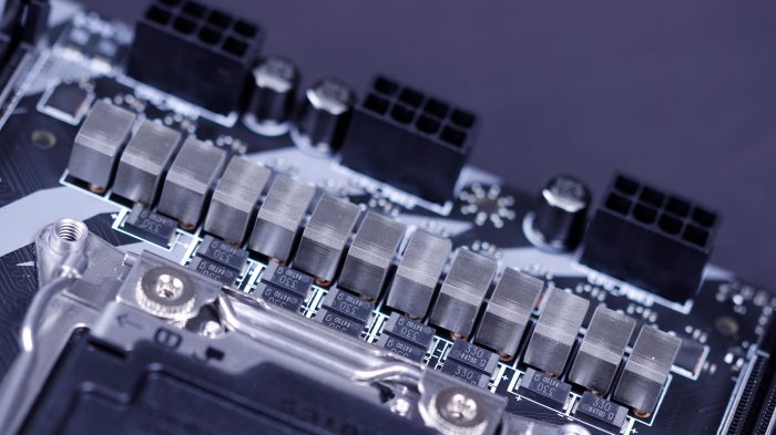
Here we get a peek at the VRM and what its made up of. The Main power stages for the CPU are TDA21472 which are 70A units. They are controlled by an International Rectifier IR 35201 which is an up to 8 phase controller. I think it goes without saying that this VRM is far sufficient for even heavily loaded 18C CPUs.
Here we take a look at the new stripped VRM with the triple power connectors.
Now follow along as we take a look at the UEFI and software
 Bjorn3D.com Bjorn3d.com – Satisfying Your Daily Tech Cravings Since 1996

