The P67A-UD7 will be the newest flagship motherboard from GIGABYTE, scheduled to be released early 2011 to go with Intel’s new Sandy Bridge architecture.
Introduction
It feels as though it has been ages since we first looked at X58 socket LGA1366 and P55 socket LGA1156 motherboards. The beefed up X58 and P55 motherboards pushed our Core i3, i5 and i7 CPUs to unbelievable speeds. With the release of Sandy Bridge just around the corner, GIGABYTE sent us their latest motherboard, tailored for the LGA1155 Sandy Bridge platform. The GIGABYTE GA-P67A-UD7 will be GIGABYTE’s flagship motherboard, competing with ASUS’ Maximus IV Extreme and MSI’s P67A-GD65 till the release of the next generation LGA2011 socket motherboards. We are expecting the board to launch in 2011, early January.
In the past, GIGABYTE has included features such as Ultra Durable 3, ON/OFF Charge and 333 Onboard Acceleration on their boards with great success. It appears that GIGABYTE is continuing this trend on the entry level motherboards as well as the top of the line P67A-UD7, and staying with the features that have brought their products such acclaim.
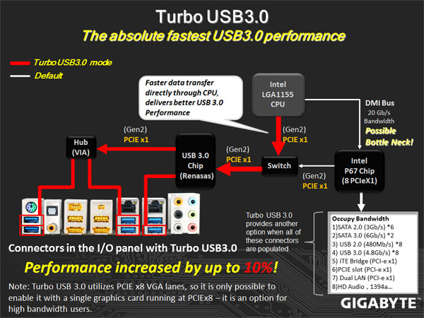
Current Intel chipsets support PCI-Express 2.0 at a lower 2.5GT/s, which limits each direction of a lane to a maximum of 250MB/s. With USB 3.0 and 6Gbps SATA interfaces connected to PCI-Express x1 slots, devices connected to these interfaces will be limited to the 250MB/s speeds. A nice change on the P67 lineup of motherboards will allow the PCI-Express slots to operate at a stunning 5GT/s, providing up to 500MB/s of bandwidth in each direction. This adds up to 1GB/s bidirectional bandwidth.
The P67A-UD7 will also have unlocked memory multipliers, making it easier to keep the CPU and Memory in exact clock frequencies that the user wants when they are overclocking. The H67 architecture motherboards will unfortunately have a locked memory multiplier, but will be able to take advantage of Intel’s integrated graphics on the Sandy Bridge CPUs, while the P67 won’t. This is why we have seen several video outputs on the H67 lineup of motherboards and none on the P67. At the moment, we do not believe that there will be a hybrid solution for the Intel Sandy Bridge built-in GPU to work together with dedicated video cards, but this is not definite and could change.
While at the moment we do not have a price tag for the P67A-UD7, we are sure it will not be cheap, considering that the last X58A-UD7 motherboard’s had an MSRP of around $340. Those want to combine a top of the line overclocking/gaming motherboard with the Sandy Bridge platform should start saving till the P67A-UD7 hits store shelves and major e-tailers. Let’s take a look at what buyers should expect from the P67A-UD7.
Special Features
- Industry’s leading 24 phase power design for maximum power delivery.
- GIGABYTE Ultra Durable™ 3 design with 2x Copper PCB to provide the stability, reliability and longevity essential to meet the power needs of high-end processors and other components running today’s most demanding applications and games.
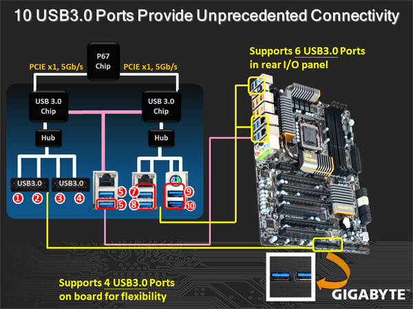
- Onboard 10 SuperSpeed USB 3.0 ports (total of 18 USB ports including USB 2.0) and 6 SATA 6Gbps to deliver impeccable data transfer speeds.
- CrossFireX™ and Nvidia® 3-Way SLI™ support for ultimate gaming experience.
- New Matte Black color PCB offering a stylish new outlook that blends itself to decoration and case mods.
- Dual Gigabit LAN with Smart Dual LAN technology offering hassle free, zero downtime and high speed network connectivity
- Unique GIGABYTE 3x USB Power design with On/Off Charge USB ports to offer faster battery charging for iPhone, iPad and iPod devices.
- GIGABYTE patented DualBIOS™ technology delivering the highest level of failure protection.
We categorized this board’s features for easier viewing. Some information has been gathered from the previous X58A-UD7 motherboard review, but we rewrote the beginning of the features section and added extra information for features that have been changed on the new P67A-UD7 motherboard. We’ll cover I/O specs and speeds on the specifications page.
Though we previously saw similar implementation of intelligent energy savings and other PWM controllers, the VRD12 Design and the Driver MOSFETs add a bit more to the P67A lineup of motherboards by having something that we have not seen on previous GIGABYTE motherboards. The implementation of the 24 phase power, the VRD12 and Ultra Durable 3 design along with the new driver MOSFETs are mainly there for extreme overclockers and gamers.
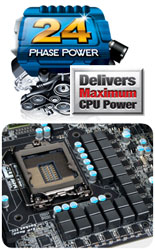 |
24 Phase Power – Unlocked Power
GIGABYTE Unlocked Power, with completely reengineered 24 phase power design able to deliver the maximum CPU power, the highest amount of power of any current desktop motherboard. GIGABYTE engineers have completely redesigned the traditional PWM power design of the motherboard to deliver first class system performance and stability.
True 24 phase power design enables optimum power delivery and low temperatures. This was mainly developed for extreme overclockers, making it possible to get a greater overclocking margin. To sum it up, 24 Phase Power helps with better power delivery and stability, lower VRM temperatures, better efficiency, and higher durability.
|
||
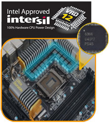 |
VRD12 Design
All GIGABYTE P67 and H67 motherboards are Intel VRD12 Qualified due to their Intel VRD12 compliant Intersil PWM controller. This allows for faster response, meaning that there won’t be delays between Analogue-Digital and Digital-Analogue conversion.
Higher accuracy is also present in V-core control because of no digitization errors.
This is a hardware design, meaning it will be stable because of no firmware crashes, and it has a greater tolerance to ESD and electrical noise, therefore reducing component damage. PWM signals are not affected.
|
||
 |
GIGABYTE Ultra Durable 3 design, featuring 2 ounces of copper for both the Power and Ground layers which dramatically lowers system temperature by delivering a more efficient spreading of heat from critical areas of the motherboard such as the CPU power zone throughout the entire PCB. GIGABYTE’s Ultra Durable 3 also lowers the PCB impedance by 50%, which helps to reduce electrical waste and further lowers component temperatures. A 2oz Copper layer design also provides improved signal quality and lower EMI (Electromagnetic Interference), providing better system stability and allowing for greater margins for overclocking…more | 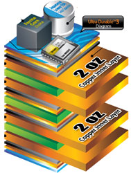 |
|
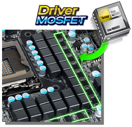 |
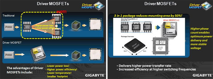
Driver MOSFET
Driver MOSFETs are completely redesigned MOSFETs combining the driver pad, the High side MOSFET pad and the Low side MOSFET pad into one component. This helps reduce mounting area by up to 50%. The Driver MOSFETs are capable of achieving lower working temperatures, higher power efficiency, and lower power loss, making current transfer much faster and smoother while still maintaining stable voltage under heavy load. |
||
 |
|||
|
Dual Power Switching
The Dual Power Switching design is for delivering better durability and longer component lifespan. When Dual Power Switching is activated, 2 sets of 12 power phases operate in tandem, automatically turning on one set of 12 phases and powering down the other 12, allowing the non active set to rest. Dual Power Switching ensures that each set of phases share the power workload, effectively doubling the lifespan of the phases.
|
|||
 |
Smart Dual LAN
GIGABYTE Smart Dual LAN technology features intelligent LAN port auto-switching between the 2 physical Gigabit LAN chips; offering hassle free, zero downtime, high speed network connectivity. With Smart Dual LAN, LAN Chip 2 automatically kicks in without requiring users to switch the network cable. |
||
|
|||
 On/Off Charge Support
GIGABYTE On/Off Charge technology that enables faster iPhone, iPad and iPod Touch charging. A derivative of GIGABYTE’s highly acclaimed 3x USB Power feature, On/Off Charge technology allows iPhone, iPad and iPod touch devices to draw more current from GIGABYTE motherboard USB ports than standard USB ports allow, with the added benefit that the PC can be on, in standby mode or even off…more |
|||
 Visible Overvoltage Reminder
Debug LEDEmbedded post code LED display simplifies motherboard signals and indicates system status
|
|||
 USB 3.0 Support
The GIGABYTE P67A series motherboards support the latest generation SuperSpeed USB 3.0 technology made possible through an onboard NEC host controller. With superfast transfer rates of up to 4.8Gbps, users are able to experience an almost a 10x improvement over USB 2.0. Additionally, backwards compatibility with USB 2.0 assures users of long term use of their legacy USB 2.0 devices. The onboard NEC SuperSpeed USB 3.0 technology also provides new power management features that include increased maximum bus power and device current draw to better accommodate power-hungry devices.
|
|||
 SATA 6 Gbps Support
Yet another onboard feature of GIGABYTE P67A motherboards are Marvell’s new SE9128 chips for high-speed SATA Revision 3.0 compatibility, delivering superfast 6Gbps link speeds for twice the data transfer rates of SATA Revision 2.0 (3 Gbps). When used in RAID 0 (Stripe) mode, GIGABYTE P67A series motherboards offer even faster data transfer rates of up to 4x the speed of current SATA interfaces.
|
|||
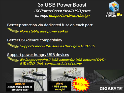
 3x USB Power Boost
GIGABYTE motherboards feature a 3x USB power boost, delivering greater compatibility and extra power for USB devices. GIGABYTE’s unique USB power design is also able to efficiently regulate output over the full voltage range, which greatly enhances USB device compatibility. In addition, dedicated lower resistance fuses ensure lower voltage drops, and provide more stable and plentiful power delivery.
  |
|||
 OV-Alert LED
4 sets of OV-Alert LEDs indicate the overvoltage level of the CPU, Memory, North Bridge and South Bridge to prevent component damage.
|
|||
 Visible Overclocking Reminder
OC-Alert LED indicates the level of CPU overclock from low to high.
|
|||
 Visible Temperature Reminder
Two sets of Temperature Alert LEDs indicate the current temperature level of the CPU and North Bridge
|
|||
|
DualBIOS™ – Patented Dual Hardware BIOS Protection
DualBIOS™ is a GIGABYTE patented technology that automatically recovers BIOS data when main BIOS has crashed or failed. Featuring 2 physical BIOS ROMs integrated onboard, GIGABYTE DualBIOS™ allows quick and seamless recovery from BIOS damage or failure due to viruses or improper BIOS updating.
|
|||
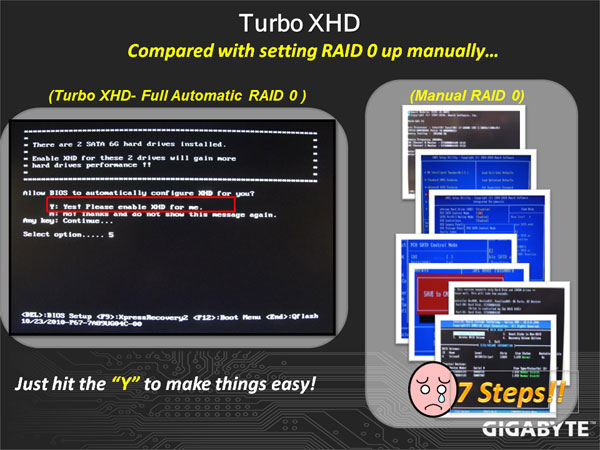
-Accelerating hard drive performance with ease") XHD (eXtreme HardDrive)-Accelerating hard drive performance with ease
Accelerating system performance is made easy with the user friendly GIGABYTE eXtreme Hard Drive (X.H.D). GIGABYTE eXtreme Hard Drive (X.H.D) provides a quick and easy way to boost your hard drive performance simply by adding another hard drive.
 |
|||
|
Multi-display support with 3 way CrossFireX and 3 way SLI™
Flexible graphics capabilities – Up to 3 VGA cards are supported for either 3 way CrossFireX™ or 3 way SLI™ action, delivering the ultimate in graphics performance for gaming enthusiasts who demand the highest frame rates without compromising on resolution.
 |
|||
 Benefits of 2 oz Copper PCB
• Cooler than traditional motherboards
• Enhanced durability • Improved energy efficiency • Greater margins for overclocking…more |
|||
|
2X Lower Impedance

In addition, doubling the amount of copper lowers the PCB impedance by 50%. Impedance is a measure of how much the circuit impedes the flow of current. The less the flow of current is impeded, the less amount of energy is wasted. For GIGABYTE Ultra Durable 3 motherboards, this means total PCB electrical waste is reduced by 50%, which also means less heat is generated. 2 ounces of copper also provides improved signal quality, providing better system stability and allowing for greater margins for overclocking. |
|||
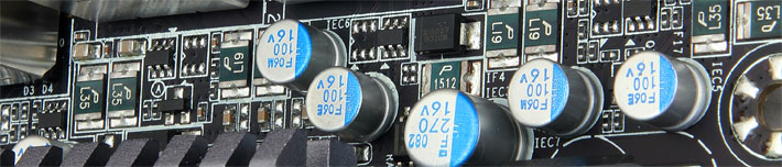
 50,000 Hours Japanese Solid Capacitors
GIGABYTE Ultra Durable motherboards are equipped with solid capacitors developed by leading Japanese manufacturers. With an average lifespan of 50,000 hours, these solid capacitors provide the stability, reliability and longevity essential to meet the power needs of high-end processors and other components running today’s most demanding applications and games…more
|
|||
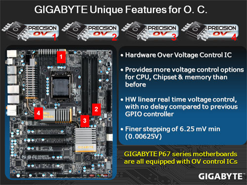
 Hardware OverVoltage Control IC – Enabling Extreme Overclocking
GIGABYTE Hardware Overvoltage Control ICs featuring more voltage control options than before for the CPU North Bridge and memory. The overvoltage controllers also provide hardware linear real-time voltage control, which means there is no delay compared to the GPIO controller in past implementations. In addition, GIGABYTE’s Hardware Overvoltage Controller ICs also allow for much finer voltage control, allowing power users to adjust voltage in as little increments as 6.25mV for better overclocking performance.
 |
|||
|
Onboard Quick Switches
Onboard Power, Clear CMOS and Reset buttons allow for quick and easy tweaking for power users working in an in chassis environment.
|
|||
|
Qualified for Windows® 7
The motherboard qualified for WHQL (Windows Hardware Quality Labs) certification of Windows 7 from Microsoft®, setting the standard for future Windows 7 certified motherboards…more
|
|||
 ErP Lot 6 support
The ErP (as known as Energy-Related Products Directive) is part of new European Union’s environment regulations. ErP established is based on the concern of environmental issues regards electronic devices been gained popularity and how to improve energy efficiency for better and greener life. GIGABYTE presents standard motherboards to help you effectively improving system performance and saving more energy.
|
|||


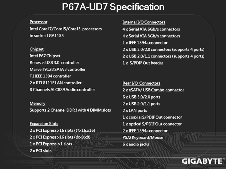
Specifications

| Specification | GIGABYTE P67A-UD7 |
|---|---|
| CPU Support | LGA 1155 Intel® 2nd Generation Core Processors |
| Chipset |
Intel® 6-series Chipset |
| Memory |
4 DIMMs Dual Channel DDR3 2200 / 1600 / 1333 / 1066 / 800 |
| Expansion Slots |
4* PCI-e x16 ( 2×16 or 4×8), 1* PCI-e x1 2* PCI |
| Storage |
4* SATA 3Gbps, 6* SATA 6Gbps, 10* USB 3.0, 8* USB 2.0, 3* IEEE1394 |
| Audio |
8-Channel Audio |
| LAN |
2* PCI-e GbE |
| Form Factor |
ATX |
| Others |
DualBIOS™, Ultra Durable™ 3, On/Off Charge, 3x USB Power |
The GIGABYTE GA-P67A-UD7 should be a very fun motherboard when it comes time to benchmark. At the moment we are very limited in terms of what information we can release, so we’ve included the P67A-UD7’s specifications here.
From what we understand, the P67A-UD7 will be the only motherboard to support 3-way SLI for now. The P67A-UD5 and UD4 motherboards will only have up to 2-way SLI support, meaning that the motherboard will not come with a 3-way SLI bridge or enough PCI-Express x16 slots for 3-way SLI support. The P67A-UD3R will not have SLI support at all. For hardcore gamers, the UD7 will be the board of choice.
The UD7 will also have 10x USB 3.0 ports, which means that almost all the USB connectors on the motherboard will be USB 3.0. USB 3.0 is backwards compatible with USB 2.0 devices, but provides 10x the performance of a USB 2.0 connector.
Software Overview

Here are some great applications that GIGABYTE includes with the P67A-UD7 motherboard. Most of these applications also come with other model motherboards, including the Intel platform X58, P55, H57, H55, P45, P43 G41 series motherboards, and AMD 800 and 700 series motherboards, so it’s not really an area that we saw an improvement on the P67 lineup of motherboards. For more information about certain features, please make sure to check on GIGABYTE’s website for updates.
From what we see from the past, it is very likely that all the new Intel platforms, including the H67, H65, Q67, and Q65 chipsets will include these software, or at least some of them.
The descriptions provided by GIGABYTE do an excellent job explaining what each of the applications do.
 Dynamic Energy Saver™ 2
GIGABYTE Dynamic Energy Saver™ 2 incorporates a host of intelligent features that use a proprietary hardware and software design to considerably enhance PC system energy efficiency, Reduce power consumption and deliver optimized auto-phase-switching for the CPU, Memory, Chipset, VGA, HDD, and fans with a simple click of button.
|
||||||||||||
 Cloud OC
GIGABYTE Cloud OC is a free overclocking application that facilitates PC overclocking through any web browsing capable device such as a smart phone, iPad, iPhone, Netbooks or notebook PC. Being browser based it connects via wireless Internet, Bluetooth or through an Ethernet cable and its many functions are categorized into three tabs: Tuner, System Info and Control…more |
||||||||||||
 Hotkey OC
GIGABYTE Hotkey OC allows users to create and save various profiles that can be adopted for different benchmarks. Hotkey OC then allows users to jump between these profiles on the fly so that the best profile for each segment within the benchmark can be used to optimize scores and boost overall performance. So, for example, when running 3DMark 06 the 1st profile might be optimized for graphics and can be used for the first two graphics tests, then the next two tests can utilize the 2nd profile which might be optimized for CPU tests, and one could jump back to the 1st profile again for the final two graphics (shader) tests…more |
||||||||||||
|
Smart 6- A Smarter way for PC system Management
GIGABYTE Smart 6™ is designed with user-friendliness in mind, and offers a combination of 6 innovative software utilities that provide easier and smarter PC system management. Smart 6™ allows you to speed up system performance, reduce boot-up time, manage a secure platform and recover previous system settings easily with a click of the mouse button.
|
||||||||||||
 AutoGreen- Greening your PC via Bluetooth cellphone
AutoGreen technology can automatically save power for you simply by your bluetooth cell phone when you are away from your computer.
Note: GIGABYTE motherboards do not include a Bluetooth® receiver; the addition of a 3rd party Bluetooth receiver is required. |
||||||||||||
 EasyTune6
GIGABYTE has completely redesigned EasyTune6 from the ground up to make it easier than ever to manage and monitor your hardware resources as well as tweak your system settings in order to achieve maximum system performance. Whether you are an overclocking enthusiast, or a computer novice, EasyTune6 provides the tools you need to quickly and effortlessly fine tune your system.
|


Unboxing the GIGABYTE GA-P67A-UD7


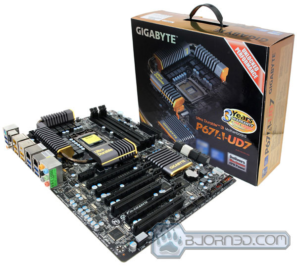
The new GIGABYTE P67A-UD7 motherboard’s box impressed us when we first saw it. Pictures don’t do the box justice, so we’ll describe it too. It has a nice black and golden scheme, and is extremely shiny. We can clearly see the new heatsink design that GIGABYTE uses on their new P67 motherboards just from looking at the box. GIGABYTE also provides USA and Canadian users with a 3 year warranty. This will ensure that if there are any problems with the motherboard in the 3 years starting from the day of the purchase, buyers will have no problems returning the motherboard for a new one. On the front cover of the box we can also see the logo of the Ultra Durable 3 motherboard design, as well as that of the latest Intel Sandy Bridge processors. The unlocked performance ribbon on the top along with the Delivers Maximum CPU Power means that the motherboard will be able to overclock the CPU to phenomenal frequencies.
The back of the box shows the features that we have talked about on Page 2. Other features that are also described on the back of the motherboard include eSATAUSB Combo ports and Hardware Precision Over Voltage Control ICs.


The motherboard’s box has a flip cover, making it possible for the buyer to check out the motherboard before they commit to buying it. The same features, and a few new ones, are also explained in the inside flap of the front cover. On the right side under the front cover we can see what looks like Intel’s new CPU cooler for the Sandy Bridge processors. The diagram shows how the new heatsink design on the motherboard has excellent cooling potential with the combination of the Intel stock cooler. The air is blown towards the motherboard, spreading out on the sides of the socket, blowing through the motherboard’s heatsinks.


The way GIGABYTE designs their top of the line motherboards boxing seems to be the new standard for manufacturers like MSI, ECS, ASUS, etc. The first few times it felt as if the motherboard was not packaged properly and not protected enough without the anti-static bag, however, after reviewing several motherboards, we found that none of them ever had any problems. The boxing on the previous pictures seems to be just a very thin layer of cardboard. We had to take out the main black box from the shiny outer packaging in order to gain access to the motherboard and accessories. The black box opens up on the side where the carrying strap is. Once it is opened up, the inside of that box contains two more boxes: one which holds the motherboard, and the other which has all the accessories to the motherboard.

The accessory box contains the following accessories. Originally the cables, and adapters are packaged in bags, but we took all the accessories out of the bags for a better look. First of all, we are a bit disappointed that while GIGABYTE changed their motherboard color design scheme from the baby blue color to the new black and golden scheme, users still receive 4x baby blue SATA cables. While it is not really a big problem, we think that even the eSATA expansion slot bracket cables with the power cable should have also been completely black. Thankfully, there are 2x black SATA cables, which is all most users will likely need, but for people who have many more drives, having mixed colors can look a bit off.
The following accessories are provided with the GIGABYTE GA-P67A-UD7 motherboard:
- Motherboard driver disk
- User’s Manual
- Quick Installation Guide
- Six SATA cables
- I/O Shiled Plate
- Dual eSATA and Power bracket
- 2-Way SLI bridge connector
- 3-Way SLI bridge connector
- 2-port SATA power cable
- GIGABYTE sticker
- Dolby Home Theater sticker
An Overview of the GA-P67A-UD7’s Design


When we first saw pictures of the P67A-UD7 motherboard during IDF 2010, most pictures made the board look a lot worst what it actually was. At first, we thought that the old baby blue design looked better, but after receiving the motherboard and taking a look at it in real life, it completely changed our views. The pictures come pretty close to the real appearance, but don’t capture that extra “oomph” that the real product has. However, this is not the only color that the new Sandy Bridge motherboards will come in. The black and gold scheme is only used on the high-end motherboards for GIGABYTE, while the old baby blue color scheme will still be used for the entry and mainstream level motherboards.


After using several non-GIGABYTE motherboards, we almost forgot how high-quality the GIGABYTE motherboards are. They usually feel slightly heavier than other motherboards, and the PCB feels much sturdier. This showcases GIGABYTE’s Ultra Durable 3 design, which still amazes us 2 years after it was first announced. The P67 LGA 1155 socket motherboards follow the P55 LGA 1156 architecture. We can see 4 DDR3 dual-channel slots, which are capable of 2200MHz frequencies, 2x PCI-Express x16 slots, and 2x PCI-Express x8 slots. The rest of the expansion slots consist of one PCI-E x4 slot, and two PCI x1 slots.


We do not like the way GIGABYTE organized the PCI-Express x16 slots on the P67A-UD7 motherboard. Here is a diagram showing which slots are capable of x16 speeds and which are only x8 slots.
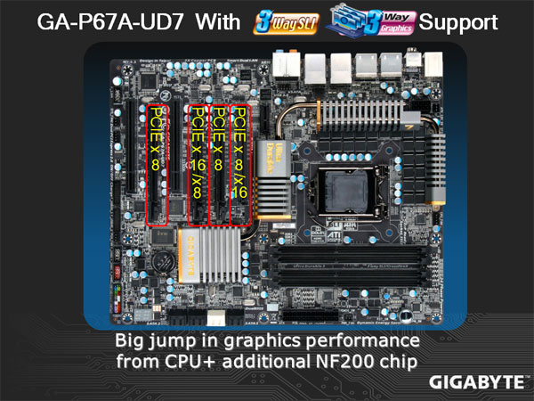
The reason why we are a bit disappointed with the expansion slot design on the P67A-UD7 is because the PCI-Express x16 slots are right next to each other, with only one other PCI-Express x8 slot in between. It would have been a much better option to allow the user to use the 4th PCI-Express slots for the second card in SLI or CrossFireX configuration with x16/x16 speeds. If the user wants to keep the x16/x16 speeds on the PCI-Express lanes, they are forced to use both video cards right next to each other. This can cause the first video card in the first PCI-Express slot to have higher temperatures than normal. Given the option of spreading out the video cards with more than just 1 slot in between, it provides more air circulation for the first card. The user can still use the first video card in the first PCI-Express x16 slot, and then use the 4th PCI-Express slot but only at x8 speeds for SLI.
On the other hand, GIGABYTE has switched the location of the last PCI-Express slot on the P67A-UD7 motherboard from the design that the X58A-UD7 had. The problem with that design was that the last PCI-Express slot was located right on the bottom of the motherboard, making it impossible to use a second video card on the bottom of the motherboard due to the 7 expansion slot limitation that most cases have.


For those who are wondering why some motherboards do not have a heatpipe heatsink design like the UD7 does, or why the new Sandy Bridge LGA1155 socket motherboards only have what seems to be a South Bridge heatsink and MOSFET heatsinks, this is actually not quite correct. The new layout of the P67 motherboards is a bit different from the previous motherboards that we reviewed. The P67 chip is actually right next to the expansion slots, where the South Bridge used to be on previous motherboards. The heatsink in the middle takes care of the NF200 chip, which is responsible for SLI support. Without the NF200 chip, 3-way SLI would not be possible. This is why the P67A-UD7 has a complete heatpipe heatsink design, whereas motherboards that don’t have the NF200 might also lack the heatpipe heatsink.
We can also see that the heatsinks on the P67A-UD7 have been fully screwed on from the back, instead of using the old push-pin design. Screwing on the heatsink is much better than just using the push-pin design, because the heatsinks have a better and sturdier contact between the chips and other components on the motherboard.
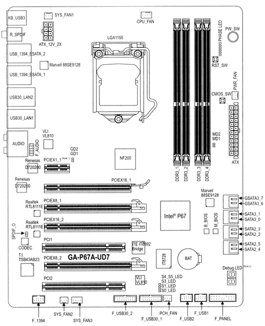
Here we have a clear overview of the motherboard and the main chips that come on the P67A-UD7 motherboard. On the next page, we’ll go into more detail about what each of these chips and connectors are responsible for.
A Closer Look at the GA-P67A-UD7


Let’s start off on the left bottom side of the P67A-UD7. The first chip that we can see is the Texas Instrument IEEE 1394 controller. As the name says, the T.I. controller controls the IEEE 1394 ports, located right below the chip. This chip allows up to 3 IEEE 1394a ports (2 on the back panel, 1 via the IEEE 1394a bracket connected to the internal IEEE 1394a header). We can see a lot of high quality components on this motherboard, including the Japanese capacitors, and overall, the motherboard has a very clean design with of the components.
In the second picture we see several smaller chips. The two chips towards the top of the second picture seem to be the NEC Renesas USB 3.0 controllers. The chip right on the bottom of the second picture is the 8 channel Realtek ALC889 Audio controller. The ALC889 codec is a Digital to Analogue converter with a 108 dB Signal-to-Noise ratio playback quality. The audio on this motherboard is also Dolby certified, meaning that the overall quality of the audio should be decent. We saw the same implementation of the ALC889 codec on the GIGABYTE X58A-UD7 motherboard. Towards the middle of the second picture, there are two more chips from Realtek. These are the RTL8111E LAN controllers. The GIGABYTE P67A-UD7 has a Smart Dual LAN technology which allows the 2nd chip to automatically kick in without requiring users to switch the network cable. This comes handy in case one of LAN chips encounters a hardware error. This means that the user will also stay connected without any downtime in case the first LAN chip encounters a hardware failure. With Teaming enabled on the chips, the user can get up to twice the performance of up to 2Gbps.


Towards the top left side of the motherboard, hiding behind the rear connectors and the MOSFET cooler, are two more chips from VLI, which also work with the USB 3.0 controllers. Looking at the same area from the other side shows several smaller components right next to the USB 3.0 and other connectors. These are USB port fuses which provide up to 4x lower resistance to ensure lower voltage drop. This allows for better USB 3.0 performance.
The GIGABYTE P67A-UD7 also has a 3x Power Boost for all the USB ports just like the X58A-UD7 had. This helps tremendously when using USB compatible power-hungry devices, that usually require two USB ports to power up, or for charging your devices like the iPhone, or iPad at a faster rate than on a system that does not have 3x the voltage running through the USB ports.


If we take a look between the PCI-Express x16 and x8 slots, we can see several rectangular switches that split the 32 PCI-E 2.0 lanes between the four PCI-E slots we see on this motherboard. This means that when users are operating two video cards in the 1st and 3rd PCI-Express x16 slots, both slots will get x16 performance (x16/x16), but in a 3-way SLI or CrossfireX configuration, the 1st PCI-Express slot will stay x16, and the 3rd and fourth will become x8 (x16/x8/x8).
On the second picture we can see several connectors. The first connector on the left side is the IEEE 1394a Firewire connector. The two connectors to the right of that are fan connectors. It is sad to see that GIGABYTE is still using 3-pin fan headers instead of the 4-pin PWM fan headers, even though competitors use only 4-pin PWM fan connectors on their top of the line motherboards.
On the far right of the second picture, there are two larger connectors, which are actually connectors for a USB 3.0 extension kit to be placed in the front of the system. We are not quite sure why these connectors were placed on the bottom of the motherboard if they are most likely going to be used at the front of the computer. It would have been better to place these connectors to the right hand side of the motherboard, close to the 24-pin power connector, for easier access when a user connects such an extension unit. It is once again very interesting to see that GIGABYTE did not provide any such USB 3.0 extension units that users could attach to the front of the PC in a 3.5″ drive bay or a 5.25″ drive bay. We’ve seen ECS, MSI, and ASUS do that on their top of the line P67 motherboards. Users who wish to use this port for the GA-P67A-UD7 have to buy their own USB 3.0 extension unit.


Thankfully, GIGABYTE disposed of the Floppy and IDE connectors they had on the X58A-UD7 motherboard. Those connectors are from the dinosaur age, and many already use only SATA devices. After the two large USB 3.0 connectors, we can see yet another 3-pin fan header, and two front USB connectors that can easily be utilized by cases that already have USB 2.0 or USB 3.0 prepared on the top or front of the case. On the far right of the motherboard, we can see the front panel connectors for the Power and Reset switches, the Power and HDD LED connectors, and the Speaker connector. Moving a bit more to the right, we can see the Debug LEDs. These come in very handy when overclocking a system or in the event of a hardware failure. The Debug LEDs will provide the user with a code that they can look up in their user’s manual, and they will be able to easily understand where the problem is. Further up, right next to the P67 chip’s heatsink, where the GIGABYTE logo is printed in gold, we can see two components that have a greenish dot on them. These are the BIOS chips. The inclusion of two BIOS chips is a fail-safe measure. In the event of a BIOS failure on one chip, the system will automatically start using the second one so the first one can be reflashed. This will save the user from the hassle of an RMA, and can make overclocking more fun and less dangerous. Unfortunately, there is no option to actually switch between the BIOS chips as we could do on the ASUS Rampage III series motherboards.


On the second picture above, we can see that the P67A-UD7 comes with a Power Switch, a Reset Switch, and even a CMOS Switch, which can come very handy for people running their motherboards on a test bench. Additional 3-pin fan header is located right next to the 24-pin motherboard power connector.
Looking at the storage connectors, there are 4x SATA 3 ports and 4x SATA II ports. The 4x black SATA ports are the SATA II ports, and the far right ports are the SATA III ports. The white SATA III ports have eXtreme Hard Drive (X.H.D.) support, allowing for faster performance and easier RAID 0 configuration. Unfortunately, the P67A-UD7 motherboard only comes with 8x SATA ports, whereas the X58A-UD7 motherboard came with 10x SATA ports. This isn’t a large concern, however, because the competition seems to have a total of 8x SATA ports as well. This should be enough ports for an average and high-end user.
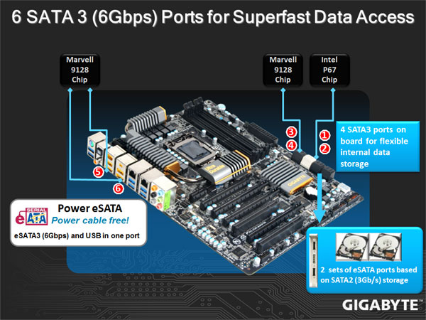
From the diagram above, we can tell that the Marvell 9128 chip controls the black SATA III ports, while the Intel P67 chip controls the white SATA III ports. The Marvell 9128 chip also controls the eSATA3 and USB in one ports.


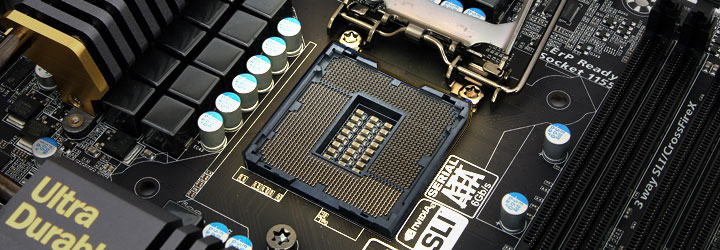
Finally, let’s take a look at the CPU socket and the surrounding components around it. From the first picture we see a PWM 4-pin CPU fan header and the VRD12 chip design right next to the MOSFET cooler. Overall we believe that the heatpipe heatsink design looks killer on this motherboard, especially with the gold colored sides. As mentioned before, right under the MOSFET coolers, there are 14 driver MOSFETs for lower power loss, higher power efficiency, lower temperatures, and for a smaller footprint. The heatsink to the far left corner of the motherboard has the number ‘7’ printed on it, representing the UD7 motherboard. Right behind the ‘7’ is the 8-pin CPU connector. We can also see a very clean design of the 24 phase power that GIGABYTE implemented on this motherboard. Though some may consider this excessive because even 16 phase power would be enough for extreme overclockers, the 24 phase power adds just a bit more stability and overall performance to the motherboard, while also making sure that it runs cooler. Is this really necessary however? Most likely not, and most users will probably not even stress the motherboard enough to fully utilize 12 phase power. The last picture shows the LGA1155 socket, which will be used by the latest Sandy Bridge processors. We’ll have performance results available when the motherboard becomes available for retail and e-tail purchase.
Final Thoughts
The GIGABYTE P67A-UD7 motherboard looks like an excellent board for hard core gamers and overclockers. The overall motherboard has a very clean and high-quality design which represents GIGABYTE’s Ultra Durable 3 motherboards really well. We can physically feel the sturdiness of the board, making it even more suitable for heavy heatsinks and other coolers.
Any overclocker, whether dabblers or hardcore, knows that motherboard temperatures and stability are the keys to a successful stable overclock. This is where GIGABYTE’s 24 power phase design, VRD 12 chip and Driver MOSFET solution come in handy. This was only seen on GIGABYTE’s previous X58A-UD7 Rev 1.0 and X58A-UD9 motherboards. These components are designed to help increase stable voltages even more, and also lower temperatures and power loss for optimal overclocking. Also, GIGABYTE’s P67 series motherboards will all come with the OV control ICs, for finer stepping of 0.00625V increments for all the main components on the motherboard, including the CPU, Memory, and the Chipset.
Reviewer’s Opinion:
I am slightly disappointed because I would have liked to see 4-pin PWM fan headers all throughout the motherboard, and not just on 2 different places. I would have also like to see a BIOS switch, which would allow me to switch from the first BIOS to the second, and of course measuring points for extreme overclockers. I find those features useful in part of my everyday overclocking experience.
Editor’s Opinion:
I found the inclusion of Smart Dual LAN chips particularly ingenuous. It solves a problem I have encountered before, where the failure of the LAN chip would crash the game I was playing. I was disappointed at the lack of the USB 3.0 extension unit for the front panel. The inclusion of the port suggests that GIGABYTE had the concept on their minds, but they seem to have taken the execution halfway, leaving out the actual extension unit itself. Though not every user will need it, the inclusion would most likely have been appreciated by the large majority of buyers.
To sum it all up, GIGABYTE took all of their previous features from their P55 and X58 motherboard series and threw it onto this P67 motherboard, with a few tweaks here and there. The major change happened on the color scheme, the heatsink design, the upgrade from 2 x USB 3.0 to 10 x USB 3.0 connectors and from 2 x SATA III to 6 x SATA III connectors. The increase of the PCIe 2.0 slots’ bandwidth to a whopping 5GT/s, providing up to 500MB/s of bandwidth in each direction was another upgrade that the current motherboards don’t have. It looks like the P67 motherboards will not have hybrid support with the CPU’s integrated graphics and another branded GPU like Nvidia or ATI, but the P67A-UD7 will have an unlocked memory multiplier, providing an easier overclocking for enthusiasts.
Tell us what you think! Participate in our discussion on the GA-P67A-UD7 HERE